Aerosol sprayer engine assembly and aerosol sprayer

An engine assembly, fog machine technology, applied in the direction of machine/engine, engine components, combustion engine, etc., can solve the problems of high power consumption, high power consumption, heavy fuel tank and equipment weight, etc., to reduce the weight of the air pump and operator difficulty, improving quality, reducing the effect of battery power

Inactive Publication Date: 2019-05-17
赵旭东
View PDF0 Cites 0 Cited by
  • Summary
  • Abstract
  • Description
  • Claims
  • Application Information

AI Technical Summary

Problems solved by technology

[0005] One is to supplement the air through the air pump and the pump. The start-up of the air pump consumes a lot of power. Generally, four batteries are needed to power the

Method used


Image

  • Aerosol sprayer engine assembly and aerosol sprayer
  • Aerosol sprayer engine assembly and aerosol sprayer
  • Aerosol sprayer engine assembly and aerosol sprayer

Examples


Embodiment 1

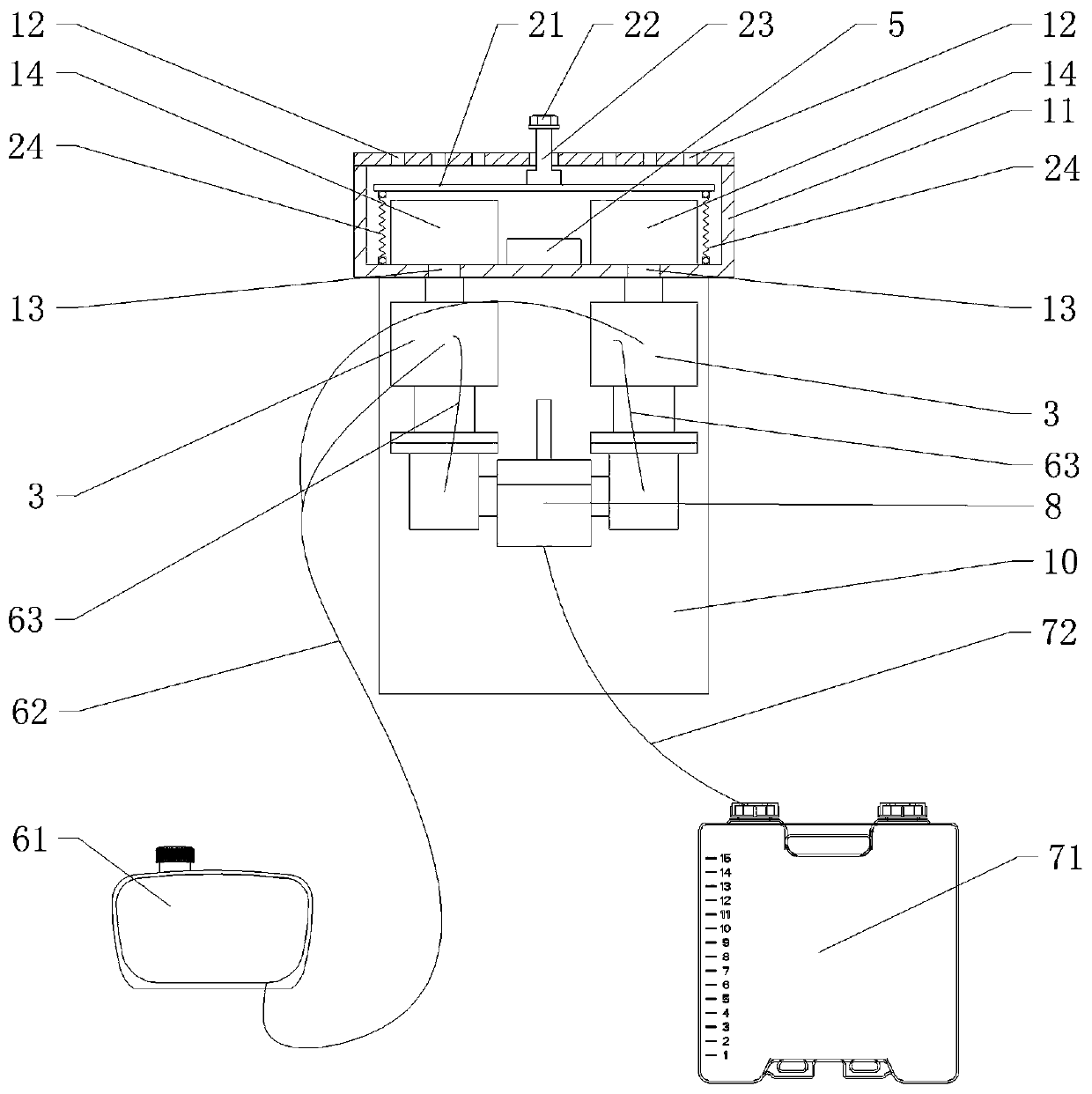
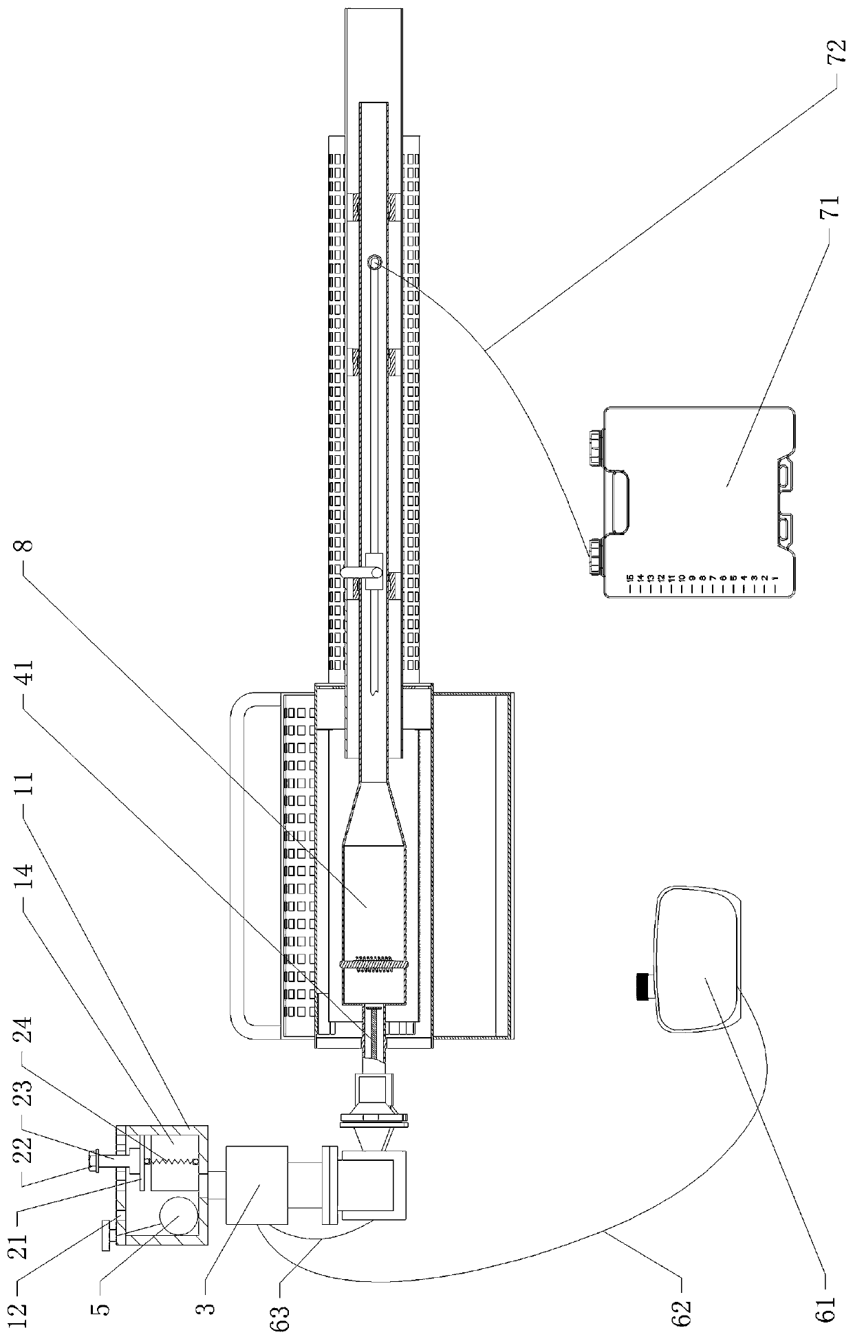
[0029] Embodiment 1: as Figure 1-3 As shown, the aerosol engine assembly includes an air supply device, an oil supply pipeline 62, a carburetor assembly, a combustion chamber, a spray pipe 73, a control device and a power supply.

[0030] The carburetor assembly is an integrated electronic ignition three-in-one carburetor assembly. The integrated electronic ignition three-in-one oiler assembly has the advantages of one-key start, one-key flameout, and carburetor atomization.

[0031] The carburetor assembly includes a carburetor atomizing device 3, an ignition device and a flameout device.

[0032] The gas supply device and the combustion chamber are respectively connected with the carburetor assembly, and the spray pipe 73 communicates with the combustion chamber.

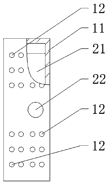
[0033] The air supply device includes an air chamber 11 , an air inlet 12 , an air outlet 13 and a fan 14 .

[0034] The air inlet hole 12 is located on the upper part of the air chamber 11 , specifically, the...

Embodiment 2

[0052] Embodiment 2: as Figure 1-5 As shown, the smoke machine includes an engine, an oil tank 61 and a medicine supply system.

[0053] The oil tank 61 communicates with the carburetor through an oil supply pipeline 62 , and the combustion chamber communicates with the carburetor through a return air pipeline 63 .

[0054] The medicine box 71 communicates with the medicine spraying pipe 73 through the medicine liquid pipe 72 .

[0055] In addition, a bracket 10 is also included for supporting devices such as the engine.

[0056] The medicine spray pipe 73 is provided with parts such as heat dissipation outside.

[0057] Engine content is with embodiment 1.

[0058] The advantages of the present invention are: the structure of the equipment room is improved, the fuel tank 61 and the medicine tank 71 are placed outside, and when in use, the weight of the fuel tank 61 and the medicine tank 71 does not need to be carried on the back, which greatly reduces the work burden.

...


PUM


Abstract

The invention provides an aerosol sprayer engine assembly and an aerosol sprayer. The aerosol sprayer engine assembly comprises a carburetor assembly and is characterized by further comprising an airsupply device, wherein the air supply device comprises an air chamber with an air inlet and an air outlet; the air inlet is communicated with the outside; the air outlet is communicated with the carburetor; a fan is arranged in the air chamber; the fan is a double-bearing fan. The aerosol sprayer engine assembly has the advantages that the structure of an equipment chamber is improved, the air pump is replaced by the fan, the battery power is greatly reduced, two batteries are used, the service life of the machine is prolonged, the weight of a new equipment chamber is about 7kg, the weight ofthe equipment and the difficulty of operators are greatly reduced, the overall quality of products is improved, the national interest is met, and energy economization and emission reduction are achieved. The invention also provides an aerosol sprayer. The aerosol sprayer has the advantages that the structure of the equipment chamber is improved, an oil box and a pesticide box are externally arranged, the weight of the oil box and the pesticide box does not need to be burdened, and the workload is greatly reduced.

Description

technical field [0001] The invention relates to a fog machine, in particular to a fog machine engine assembly and a fog machine. Background technique [0002] The fog machine is a machine that can generate smoke, and it is a spraying machine for the technology of spraying medicine. Smoke drug-loading technology is an effective and fast method of prevention and control of flies, reptiles and disinfection. It atomizes the medicine into smoke through the smoke generating device. The diameter of the smoke droplet is generally less than 50 μm, which is very small, can be filled in a certain space, can be suspended in the air for a long time, and spread very evenly to the control space. , can go deep into the gaps that cannot be reached by the mist of the general spray or the powder particles of the powder spray, and eliminate the pests and diseases through contact killing and fumigation. The smoke-loaded medicine technology is used to prevent and control plant diseases and inse...

Claims


Application Information

Patent Timeline
IPC IPC(8): F01N5/02F02B63/06F02M19/00F02M37/00A01M7/00
CPCY02T10/12
Inventor 赵程赵旭东
Owner 赵旭东
Why Eureka
Try Eureka