
Aerosol spray dispenser tank

An aerosol and spray can technology, applied in spraying devices, liquid spraying devices, packaging, etc., can solve the problems of small final product-producer ratio, user injury, and the top of the generant container falling off, etc.

Inactive Publication Date: 2005-10-19
罗伯特 H 阿布普拉纳尔普
View PDF10 Cites 0 Cited by
  • Summary
  • Abstract
  • Description
  • Claims
  • Application Information

AI Technical Summary

Problems solved by technology

First, the injector must ensure that the generant container does not rupture and cause injury to the user
Second, such injectors must ensure that the generant does not inadvertently enter the product container if the actuator becomes blocked or due to an improperly designed position of the generant container, resulting in rupture of the product container and injury to the user
In some prior art, the generant container is the outer container, so that the phenomenon of rupture can cause immediate injury to the user
Although other prior art places the generating agent chamber inside the product container, no corresponding device is provided to prevent the generating agent from finding a way to enter when the actuator nozzle is blocked or the position of the valve-generating agent container is unreasonable. Paths within the product chamber that could potentially lead to cracking or minimize the final product-to-generator ratio that is sprayed
Some other such prior art variously provide complicated and / or inappropriate means for suspending the generant container inside the product container, which have the potential to come off the top of the generant container and allow Leakage of generant from generant container into product container through valve seal; complex design for generant valve and product valve; no valve to close product container when injector is not in use; improper venturi construction; and / or lack of means to pressure fill generant containers

Method used


Image

  • Aerosol spray dispenser tank
  • Aerosol spray dispenser tank
  • Aerosol spray dispenser tank

Examples


Embodiment Construction

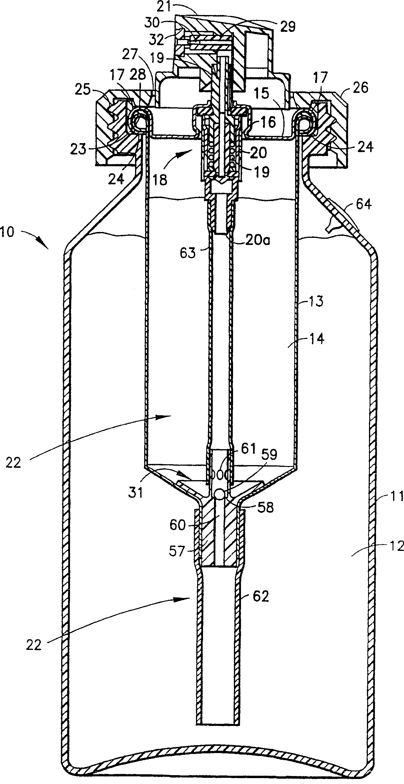
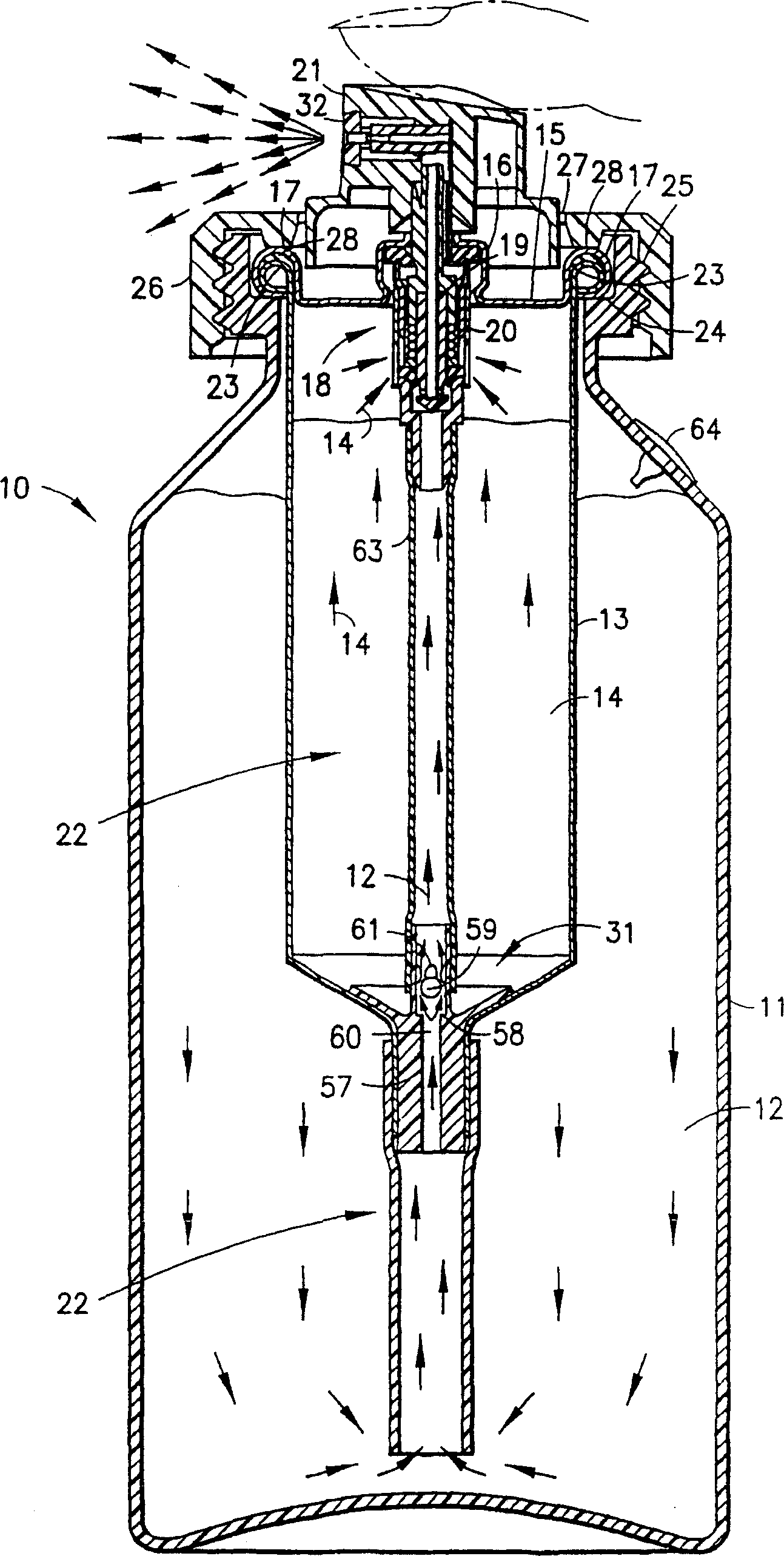
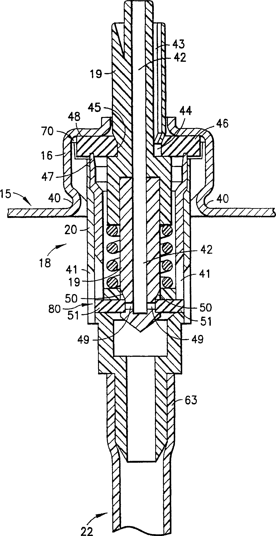
[0020] figure 1 with 2 An aerosol spray can 10 is generally shown having a thin flexible plastic outer container 11 for containing a product 12 to be sprayed. Container 11 can be molded from a variety of plastics in a variety of shapes, sizes and colors to meet market needs. Various graphic characters can also be easily pasted on the outside of the plastic container 11 . The outer container 11 will not hold the pressurized generant, so thin walls are used to reduce manufacturing costs since no substantial wall thickness is required to resist deformation or possible rupture by the generant. Products to be sprayed may include household products, pesticides, herbicides, cosmetics, paints, and the like.

[0021] The inner container 13 is placed inside the outer container 11, and is used to contain a liquid generant 14, which has a liquid phase and an upper layer of a gaseous phase. The inner container 13 will be substantially rigid to withstand deformation under the action of ...


PUM


Abstract

A dual receptacle aerosol sprayer (10) with a thin, flexible plastic outer receptacle (11) for product (12) and a substantially rigid inner receptacle (13) for propellant (14) seated within the outer receptacle (11). A closure (15) closes the inner receptacle (13) and contains a valve assembly (18). Primary propellant and secondary product valves (70, 80) in the valve assembly (18) control flow from the inner and outer receptacles (11, 13) up propellant and product valve stem bores (42, 43) into an actuator (21) having an aspirating nozzle insert (29) with a Venturi constriction (30). A conduit (22) extends from the valve assembly (18) through the inner receptacle (13) and into the outer receptacle (11). To avoid propellant overloading and rupture of the outer receptacle (11), a one-way tertiary valve (31) downstream of the secondary product valve (80) closes on clogging of the actuator discharge outlet (32) to prevent, during actuation, misdirected propellant flow from the actuator (21) and through the stem product bore (42) and the secondary product valve (80), from entering the outer product-containing receptacle (11).

Description

technical field [0001] The present invention relates to hand-held sprayers (sprayers) for spraying various aerosol products, and more particularly to dual-container sprayers, which have a first container for holding the product to be sprayed, and a second container for holding the product to be sprayed. Pressurized generator to spray the product in the second container. Background technique [0002] Various types of dual-container injectors are known, including: injectors with containers arranged side-by-side; injectors with piggyback containers, in which the propellant container is placed on top of the product container; Sprayers placed inside product containers to form inner and outer containers. A unique advantage of such dual-container injectors is that they are suitable for utilizing less generant and achieving higher product-to-generator ratios at the discharge outlet, compared to commonly used aerosol generants such as those Given the cost and environmental concerns...

Claims


Application Information

Patent Timeline
Patent Type & Authority Patents(China)
IPC IPC(8): B65D83/16B05B7/04B05B9/04B65D83/14B65D83/28B65D83/42B65D83/58
CPCB65D83/66B05B7/2424B65D83/205B65D83/14
Inventor 罗伯特·H·阿布普拉纳尔普
Owner 罗伯特 H 阿布普拉纳尔普
Learn More