
Circumferential aerosol device

a technology of circumferential aerosol and airway, which is applied in the direction of medical devices, inhalators, medical devices, etc., can solve the problems of low fraction of olfactory drug exposure for drugs carried along the breath path, no suitable nasal delivery device that is sufficiently targeted, and rapid and direct uptake into the brain

Active Publication Date: 2011-03-03
UNIV OF WASHINGTON CENT FOR COMMERICIALIZATION
View PDF37 Cites 52 Cited by
  • Summary
  • Abstract
  • Description
  • Claims
  • Application Information

AI Technical Summary

Benefits of technology

This summary is provided to introduce a selection of concepts in a simplified form that are further described below in the Detailed Description. This summary is not intended to identify key features of the claimed subject matter, nor is it intended to be used as an aid in determining the scope of the claimed subject matter.

Problems solved by technology

Depositing therapeutic drugs on the olfactory epithelium has been shown to lead to rapid and direct uptake into the brain.
Currently there are no suitable nasal delivery devices that sufficiently target the olfactory region of the nasal cavity while avoiding the lungs and respiratory area of the nasal cavity.
In addition, when a subject breaths in through the nose, the inhaled air travels primarily along the lower part of the nasal cavity into the trachea and lung, thus, leaving the air in the olfactory region mainly undisturbed and stagnant in the olfactory region (and hence leading to a low fraction of olfactory drug exposure for drugs carried along the breath path).

Method used


Image

  • Circumferential aerosol device
  • Circumferential aerosol device
  • Circumferential aerosol device

Examples


example 1

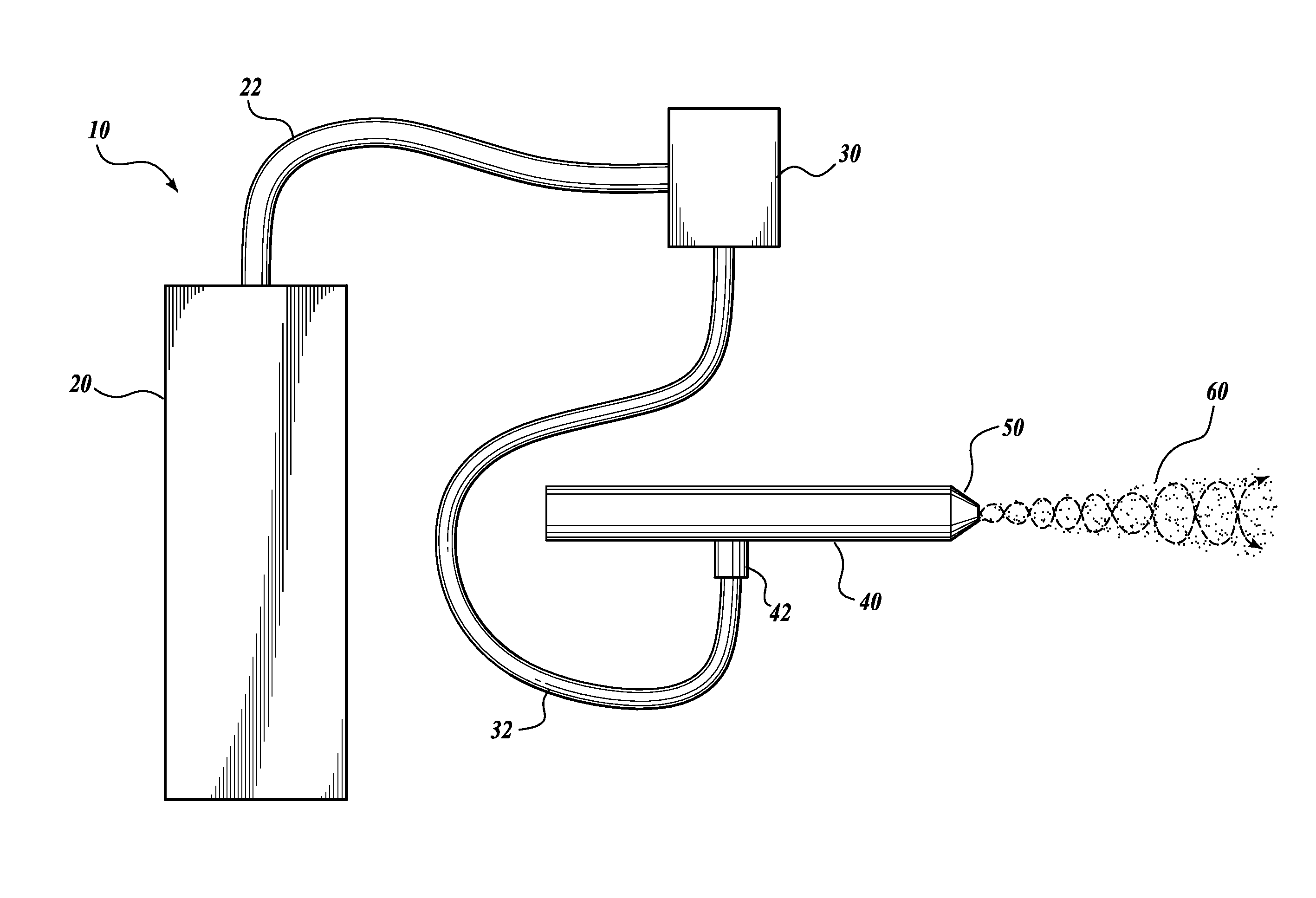
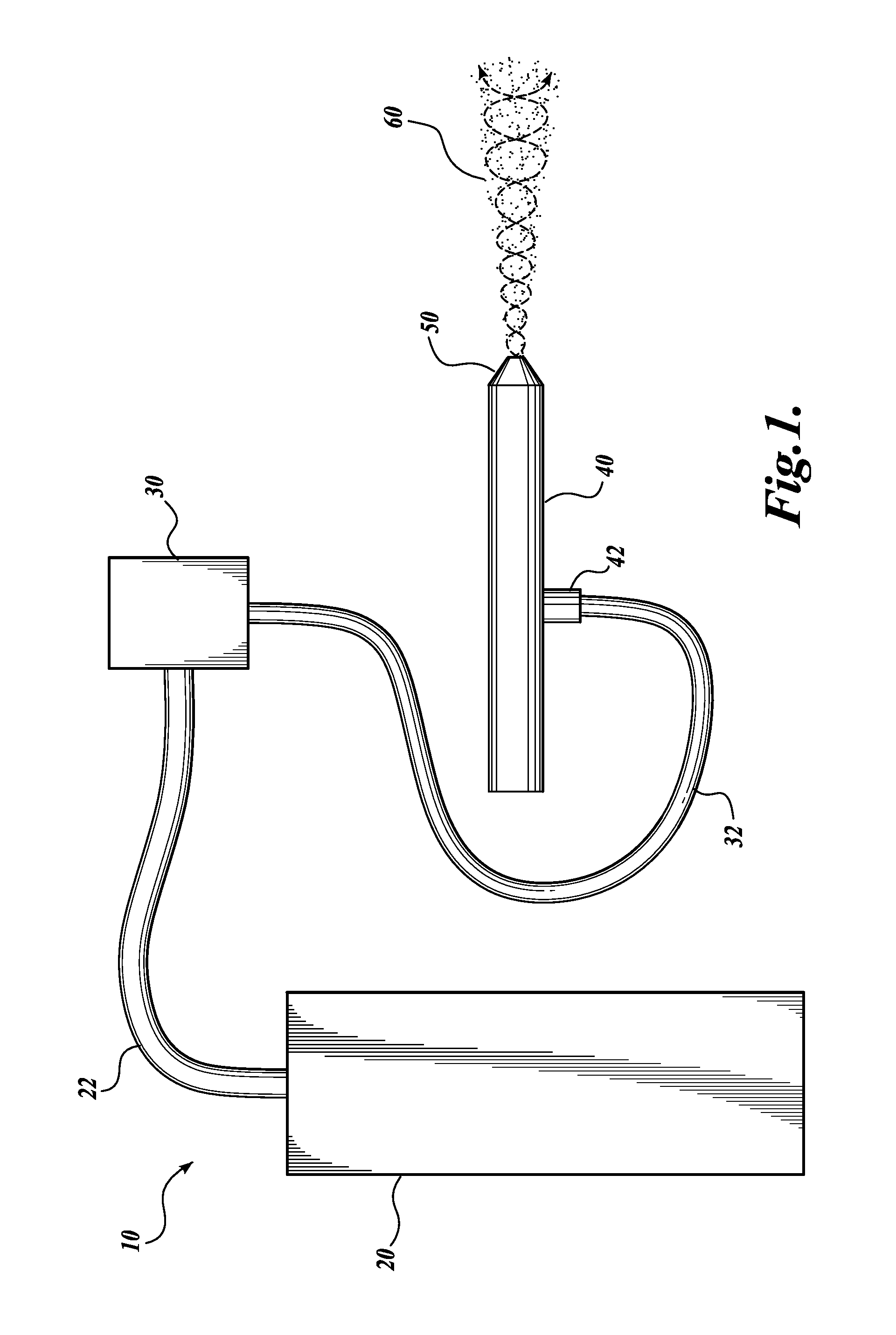
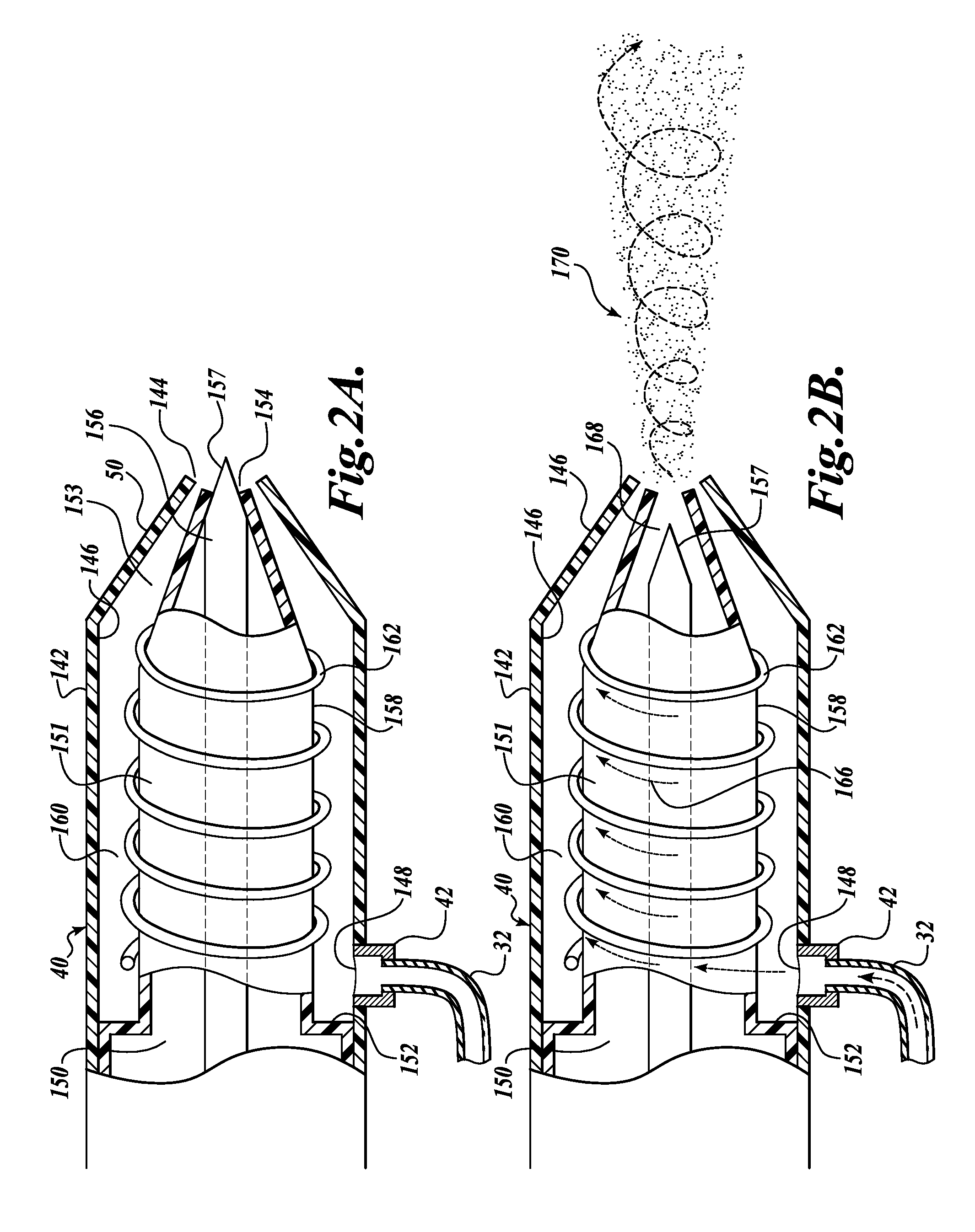
This example describes various functional parameters of the device illustrated in FIGS. 1 and 2.

The spray rate was tested by varying the driving pressure from 1 to 6 pounds per square inch and the diameter of the orifice 154. The spray rates were reproducible and within the desired range for human application, namely less than 50 microliters per second.

FIG. 9 shows the particle size distribution when water was sprayed from the device into viscous oil at a distance of 2 cm and 4 psi, and the resulting droplet diameters were measured using a microscope with size analysis software. A total of 199 measurements were made. The distribution shows that the device produces particles having diameters of from 5 to greater than 50 microns, and that the majority of the particle diameters are between 5 and 20 micrometers, with an average diameter of 11.2 microns. The size distribution obtained by this method of atomization is therefore desirable for nasal spray applications.

FIG. 10 shows the pene...

example 2

This example demonstrates the improved penetration of a simulated nose cone using a device comprising a plurality of outlets in comparison to a device having a single outlet with and without circumferential flow.

Methods:

Flow simulations were carried out using the Star-CCM+ computational fluid dynamics simulation software package (CD-adapco), version 3.06.006. In the simulation, a cone was used with similar geometry to a nasal cavity for the sake of simplicity. The cone was designed to be narrow towards the top with the only outlet for residual air located at the bottom of the cone. Thus, the air in the top of the cone was stagnant and had to be displaced in order for the nozzle flow to penetrate the top of the cone, much like the upper nasal cavity of a human. The dimensions of the cone were 7.5 cm from top to bottom, in order to realistically simulate nasal delivery to the olfactory epithelium of a human.

The following nozzle structures were tested:

(1) a nozzle without circumferenti...


PUM


Abstract

The present application discloses devices and methods for delivering a therapeutic compound to the olfactory epithelium of an animal or human. The device having one or more channels for imparting a circumferential and axial velocity to the discharged fluid, and an outlet that discharges an aerosol spray having a circumferential and axial velocity as it enters the nasal cavity of a user. The device is designed to displace the air in the upper nasal cavity in order to specifically deposit a therapeutic agent on the olfactory epithelium while minimizing pressure and discomfort experienced by the user.

Description

BACKGROUNDDepositing therapeutic drugs on the olfactory epithelium has been shown to lead to rapid and direct uptake into the brain. This direct nose-to-brain delivery route bypasses the blood-brain-barrier, which keeps a majority of drugs or drug candidates from reaching the brain in any significant concentrations. Many studies, including those of the present inventors, have shown that depositing a drug on the olfactory epithelium, while minimizing drug absorption on the respiratory epithelium, is key to maximizing the fraction of drug that bypasses the blood-brain-barrier and reaches the brain.Currently there are no suitable nasal delivery devices that sufficiently target the olfactory region of the nasal cavity while avoiding the lungs and respiratory area of the nasal cavity. The olfactory region is a narrow space at the top of the nasal cavity taking up about 10% of the total surface area of the nasal cavity. In addition, when a subject breaths in through the nose, the inhaled ...

Claims


Application Information

Patent Timeline
Patent Type & Authority Applications(United States)
IPC IPC(8): A61M11/04A61M15/08
CPCA61M15/00A61M15/009A61M15/08A61M2206/14A61M31/00B05B7/0861B05B7/0869B05B7/10A61M11/06B05B7/0892A61M2206/16
Inventor HOEKMAN, JOHN D.HO, RODNEY J.Y.
Owner UNIV OF WASHINGTON CENT FOR COMMERICIALIZATION
Learn More