Power storage apparatus and cooling system

a technology of power storage and cooling system, which is applied in the direction of non-aqueous electrolyte cells, cell components, electrochemical generators, etc., can solve the problems of shortened battery life and reduced battery performance, and achieve the effect of improving the heat radiation efficiency of the power storage uni

Active Publication Date: 2010-03-11
TOYOTA JIDOSHA KK
View PDF4 Cites 9 Cited by
  • Summary
  • Abstract
  • Description
  • Claims
  • Application Information

AI Technical Summary

Benefits of technology

[0020]According to the present invention, the power storage unit and the cooling fluid are housed in the case and the cooling fluid is brought into contact with at least the electrode element, which enables efficient transfer of the heat generated in the power storage unit to the case through the cooling fluid to improve the heat radiation efficiency of the power storage unit.

Problems solved by technology

In the power storage apparatuses, the battery performance may be reduced or the battery life may be shortened due to heat generation of the battery or the like in charge and discharge.

Method used


Image

  • Power storage apparatus and cooling system
  • Power storage apparatus and cooling system
  • Power storage apparatus and cooling system

Examples


embodiment 1

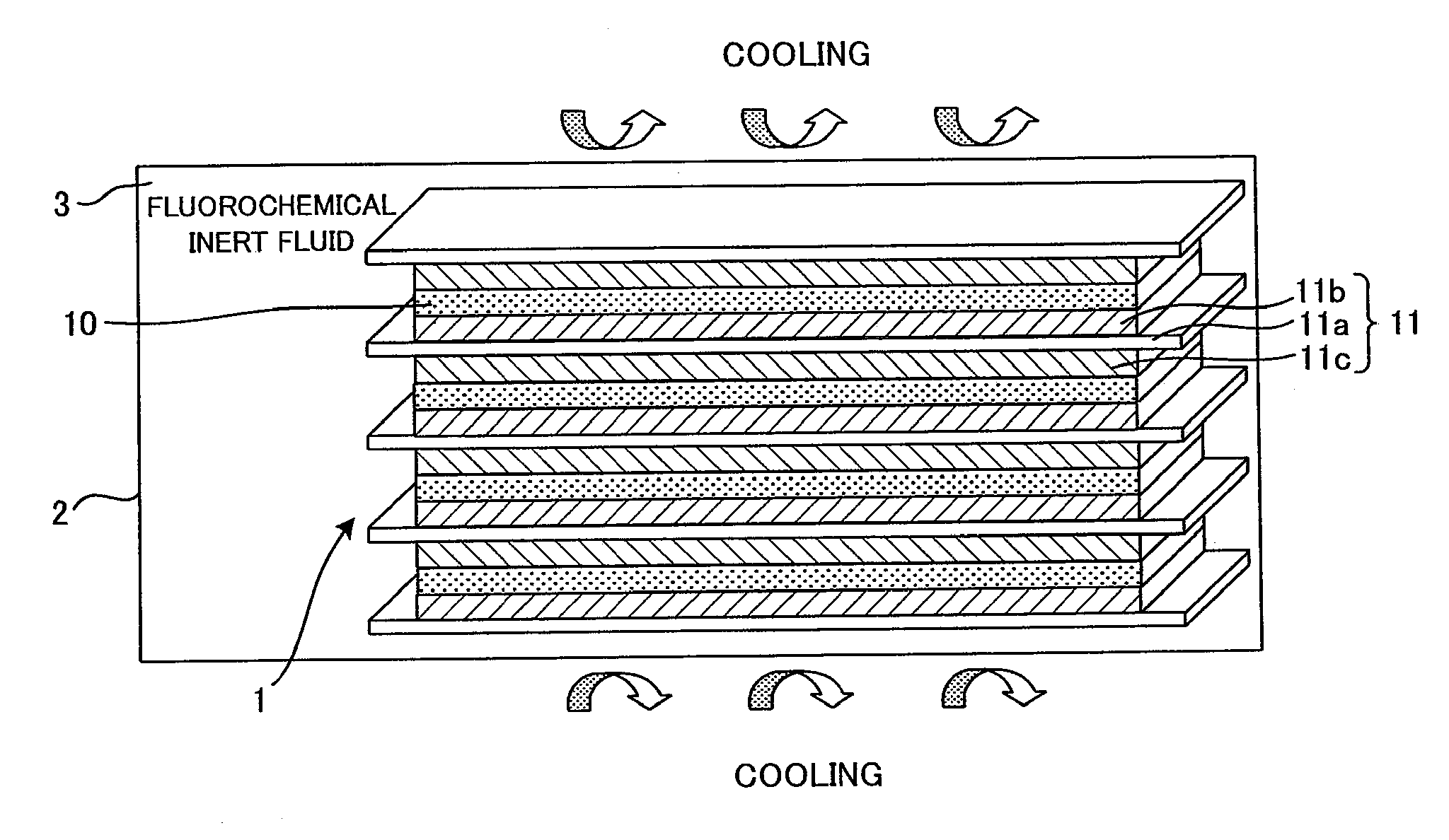
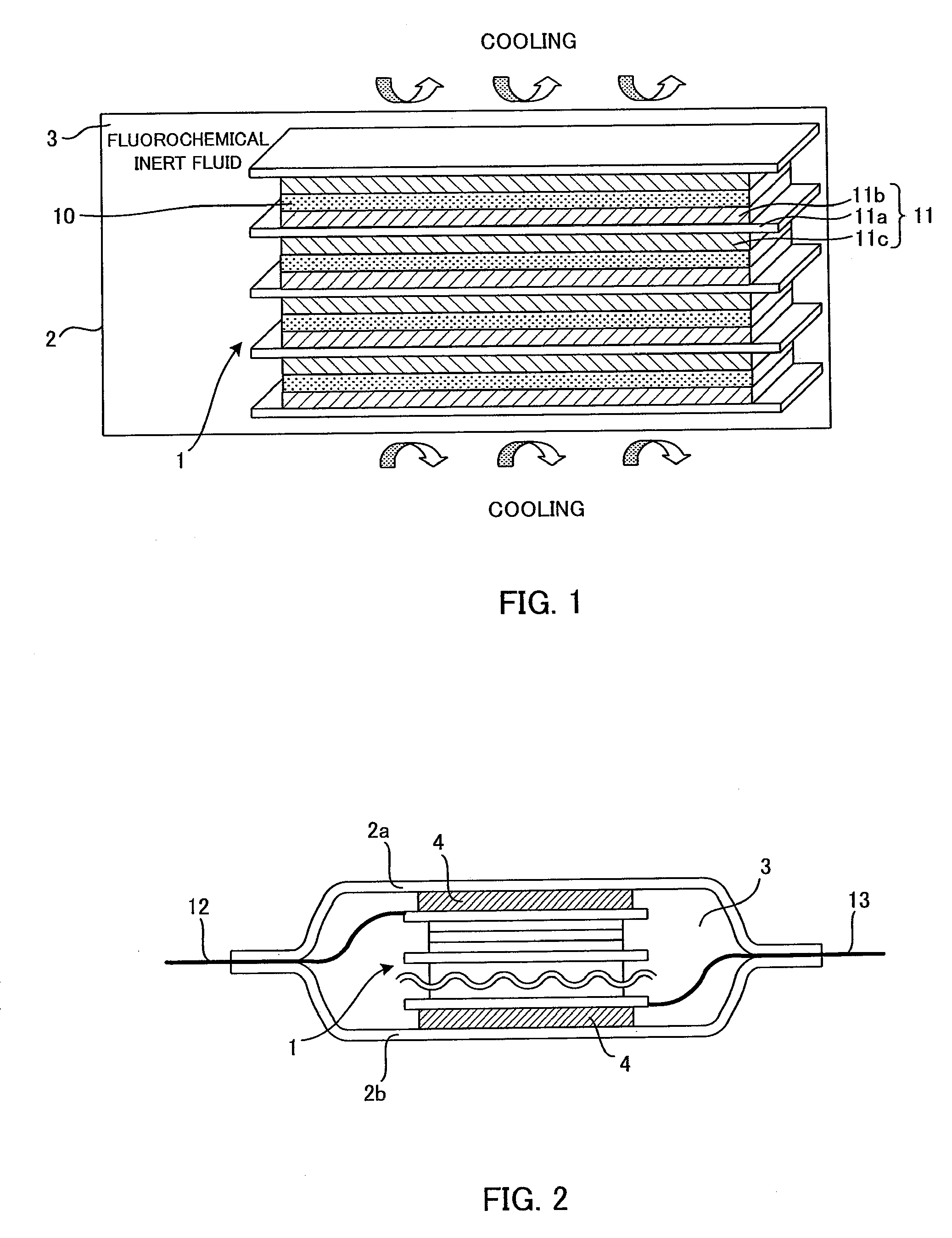
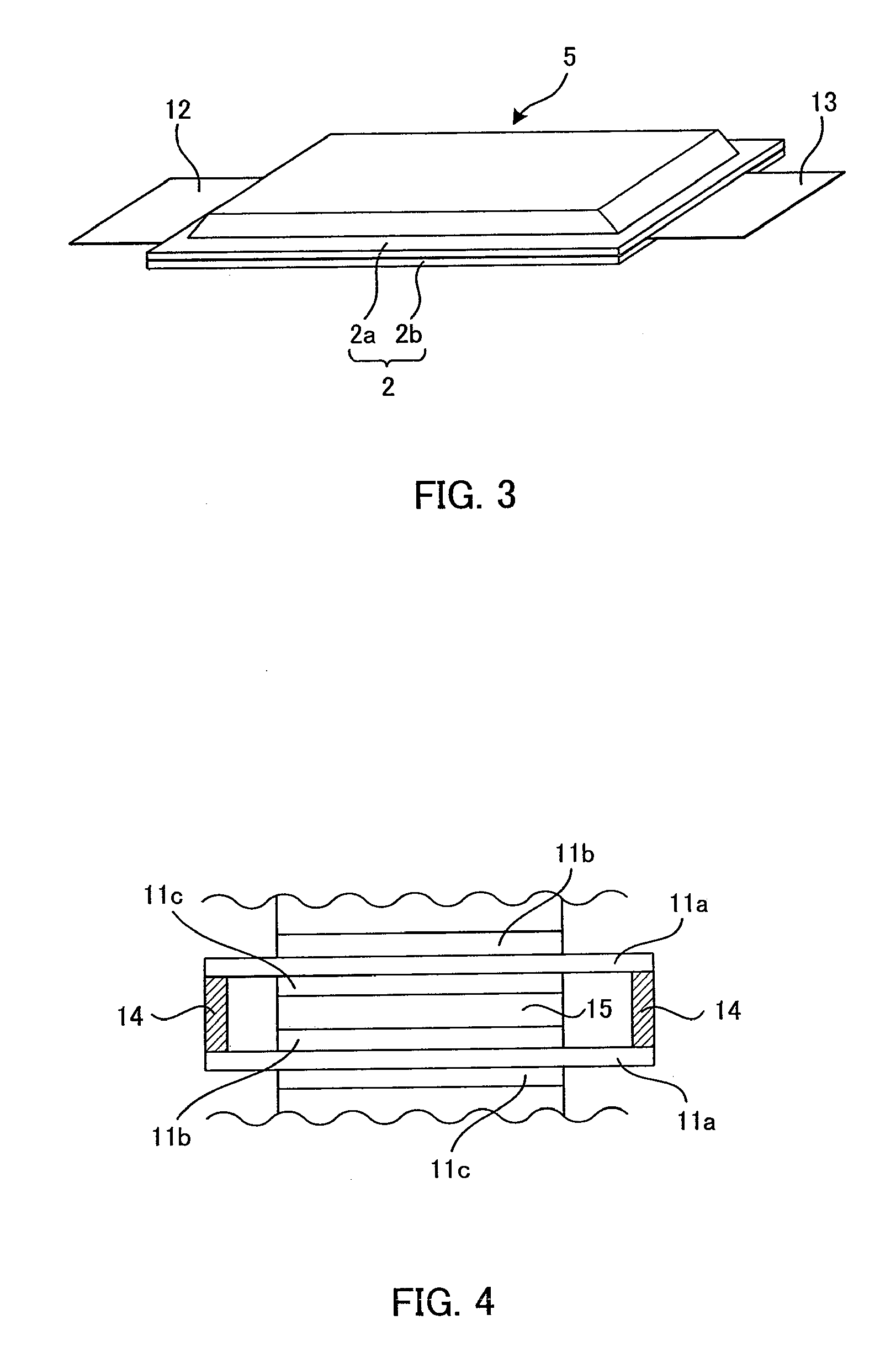
[0027]A power storage apparatus which is Embodiment 1 of the present invention will be described with reference to FIGS. 1 to 3. FIG. 1 is a side view showing the schematic configuration of the power storage apparatus. FIG. 2 is a section view showing the internal configuration of the power storage apparatus. FIG. 3 is a perspective view showing the outer appearance of the power storage apparatus.

[0028]As shown in FIG. 1, a power storage unit 1 serving as a power generation element has a structure in which a plurality of electrode elements 11 are stacked with solid electrolyte layers 10 interposed therebetween. While a secondary battery is used as the power storage unit 1 in Embodiment 1, an electric double layer capacitor (condenser) may be used.

[0029]Each of the electrode elements 11 includes a collector 11a, a positive electrode layer 11b formed on one surface of the collector 11a, and a negative electrode layer 11c formed on the other surface (opposite to the one surface) of the...


PUM

PropertyMeasurementUnit
structureaaaaaaaaaa
heat radiation efficiencyaaaaaaaaaa
ionic conductionaaaaaaaaaa

Abstract

To provide a power storage apparatus which can achieve improved heat radiation of a power storage unit, a power storage apparatus has a power storage unit including an electrode element placed with an electrolyte layer, and a case housing the power storage unit and a cooling fluid which is used for cooling the power storage unit and is in contact with at least the electrode element.

Description

TECHNICAL FIELD[0001]The present invention relates to a power storage apparatus which houses in a case a power storage unit including an electrode element placed with an electrolyte layer and which allows improved efficiency of heat radiation of the power storage unit.BACKGROUND ART[0002]Power storage apparatuses such as a secondary battery and an electric double layer capacitor (condenser) have conventionally been used as batteries in hybrid vehicles and electric vehicles. In the power storage apparatuses, the battery performance may be reduced or the battery life may be shortened due to heat generation of the battery or the like in charge and discharge.[0003]To address this, a proposal has been made in which a power storage apparatus is cooled by supplying air or the like for cooling to a case which houses the power storage apparatus. Another proposal is to fill a cooling fluid into a sealed container which houses an assembled battery including a plurality of connected battery cel...

Claims


Application Information

Patent Timeline
Patent Type & Authority Applications(United States)
IPC IPC(8): H01M10/50H01M10/613H01G2/08H01G11/00H01G11/08H01G11/12H01G11/18H01G11/22H01G11/54H01G11/56H01G11/78H01G11/80H01G11/82H01M10/05H01M10/0562H01M10/0565H01M10/60H01M10/625H01M10/647H01M10/653H01M10/6551H01M10/6563H01M10/6568H01M10/659
CPCH01G9/0003H01G9/155H01M10/5004Y02T10/7022H01M10/5032H01M10/5075H01M10/5089H01M10/5016H01M10/625H01M10/647H01M10/6567H01M10/613H01M10/659Y02T10/70Y02E60/10H01G11/56H01G11/18H01G11/78H01G11/80H01G11/82H01G2/08
Inventor TAKAGI, MASARU
Owner TOYOTA JIDOSHA KK
Why Eureka
Try Eureka