Illumination system and display device

Active Publication Date: 2010-03-18
SIGNIFY HLDG BV
View PDF6 Cites 45 Cited by
  • Summary
  • Abstract
  • Description
  • Claims
  • Application Information

AI Technical Summary

Benefits of technology

[0007]It is an object of the invention to provide an il

Problems solved by technology

A drawback of the known illumination system is that a color temp

Method used


Image

  • Illumination system and display device
  • Illumination system and display device
  • Illumination system and display device

Examples


Embodiment Construction

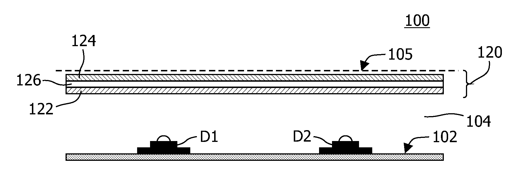
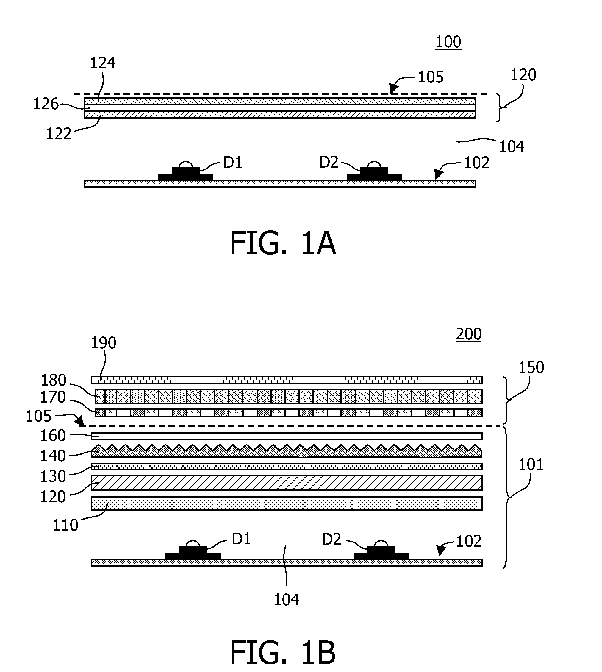
[0037]FIG. 1A shows a simplified cross-sectional view of an illumination system 100 according to the invention. The illumination system 100 according to the invention comprises LEDs D1, D2 arranged on a reflective surface 102 of a light-mixing chamber 104 of the illumination system 100. The LEDs D1, D2 emit a first primary color, for example, a primary color blue 72, 75 (see FIGS. 2A, 3A, 4A) which impinges on the luminescent layer 120. The luminescent layer 120 comprises a garnet luminescent material comprising at least Lutetium, Cerium, Silicon and Nitrogen 73, or comprises a combination of a garnet luminescent material comprising at least Lutetium and Cerium 70 and a garnet luminescent material comprising at least Cerium and at least one element of the group comprising Yttrium and Gadolinium. Examples of these different luminescent materials are represented by (Y3-x-yLuxGdy)(Al5-zSiz)(O12-zNz):Ce and comprise, for example, LuAG:Ce 70, LuAGSN:Ce 73, YAG:Ce 71, YGdAG:Ce, YAGSN:Ce 7...


PUM


Abstract

The invention relates to an illumination system, a luminaire and a display-device (200) comprising the illumination system. The illumination system (100, 101) comprises a light emitting diode (D1, D2), a light exit window (105) and a luminescent layer (120) arranged between the light emitting diode and the light exit window. The light emitting diode emits light of a first primary color (72, 75). The luminescent layer is arranged between the light emitting diode and the light exit window for converting part of the light emitted by the light emitting diode into light of a second primary color. The luminescent layer comprises a garnet luminescent material comprising at least Lutetium, Cerium, Silicon and Nitrogen (73), or it comprises a combination of a garnet luminescent material comprising at least Lutetium and Cerium (70) and a garnet luminescent material comprising at least Cerium and at least one element of the group comprising Yttrium and Gadolinium (71, 74). The light exit window emits light generated by the illumination system towards the display device.

Description

FIELD OF THE INVENTION[0001]The invention relates to an illumination system comprising a light emitting diode, a light exit window and a luminescent layer.[0002]The invention also relates to a luminair and a display device.BACKGROUND OF THE INVENTION[0003]Such illumination systems are known per se. They are used, inter alia, as luminair for general lighting purposes, for example, for office lighting or shop lighting, for example, shop window lighting or lighting of (transparent or semi-transparent) plates of glass or (transparent) plates of glass or (transparent) synthetic resin on which items, for example jewelry, are displayed. In addition, such illumination systems are used for general lighting purposes, such as for large-area direct-view light emitting panels such as applied, for instance, in signage, contour lighting, and billboards.[0004]Such known illumination systems are also used as backlight-emitting panels in (image) display devices. Such illumination systems can particul...

Claims


Application Information

Patent Timeline
IPC IPC(8): F21V9/16
CPCC09K11/0883C09K11/7774H05B33/14G02F2001/133614G02F1/133603G02F1/133614C09K11/77748G02F1/1335
Inventor HOELEN, CHRISTOPH GERARD AUGUSTWEGH, RENE THEODORUSBROERE, JANHAENEN, LUDO
Owner SIGNIFY HLDG BV
Why Eureka
Try Eureka