Self-referencing radar pulse detector

a pulse detector and self-referencing technology, applied in pulse techniques, instruments, amplitude demodulation, etc., can solve the problems of cfd showing latency errors, range measurement errors, and particular latency errors, and achieve accurate, simple and inexpensive effects, and zero latency

Inactive Publication Date: 2010-03-25
MCEWAN TECH
View PDF18 Cites 20 Cited by
  • Summary
  • Abstract
  • Description
  • Claims
  • Application Information

AI Technical Summary

Benefits of technology

[0010]Objects of the present invention are: (1) to provide an amplitude-independent automatic pulse detector that is accurate, simple, and inexpensive; (2) to provide an amplitude-indepe...

Problems solved by technology

Radar echo pulses exhibit large amplitude variations, depending on target size, range and dielectric constant, and these variations produce range measurement errors when the pulses are detected with a fixed threshold detector.
Unfortunately, the CFD exhibits latency errors caused by slow peak tracking when the pulses decrease in amplitude.
Latency is a particular problem when the CFD is used in a TDR level sensor for sloshing liquids in a tank, such as an automotive gas tank.
Another potential problem with the peak detector is it can erroneously lock-on to the strongest peak in...

Method used


Image

  • Self-referencing radar pulse detector
  • Self-referencing radar pulse detector
  • Self-referencing radar pulse detector

Examples


Embodiment Construction

[0014]A detailed description of the present invention is provided below with reference to the figures. While illustrative parameters and embodiments are given, other embodiments can be constructed with other parameters.

General Description

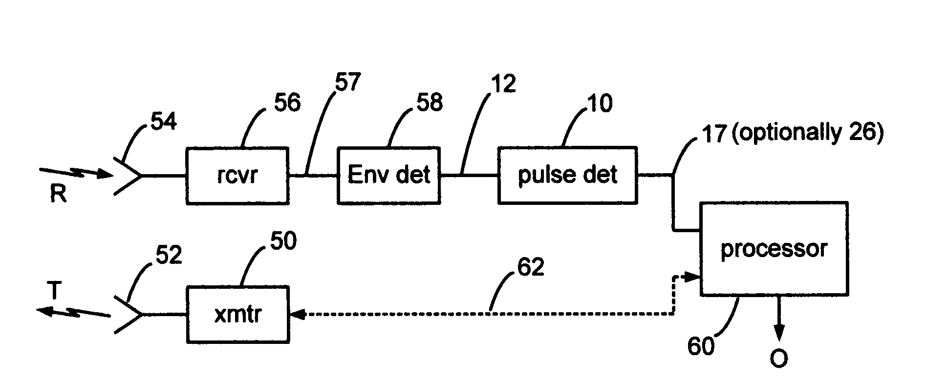
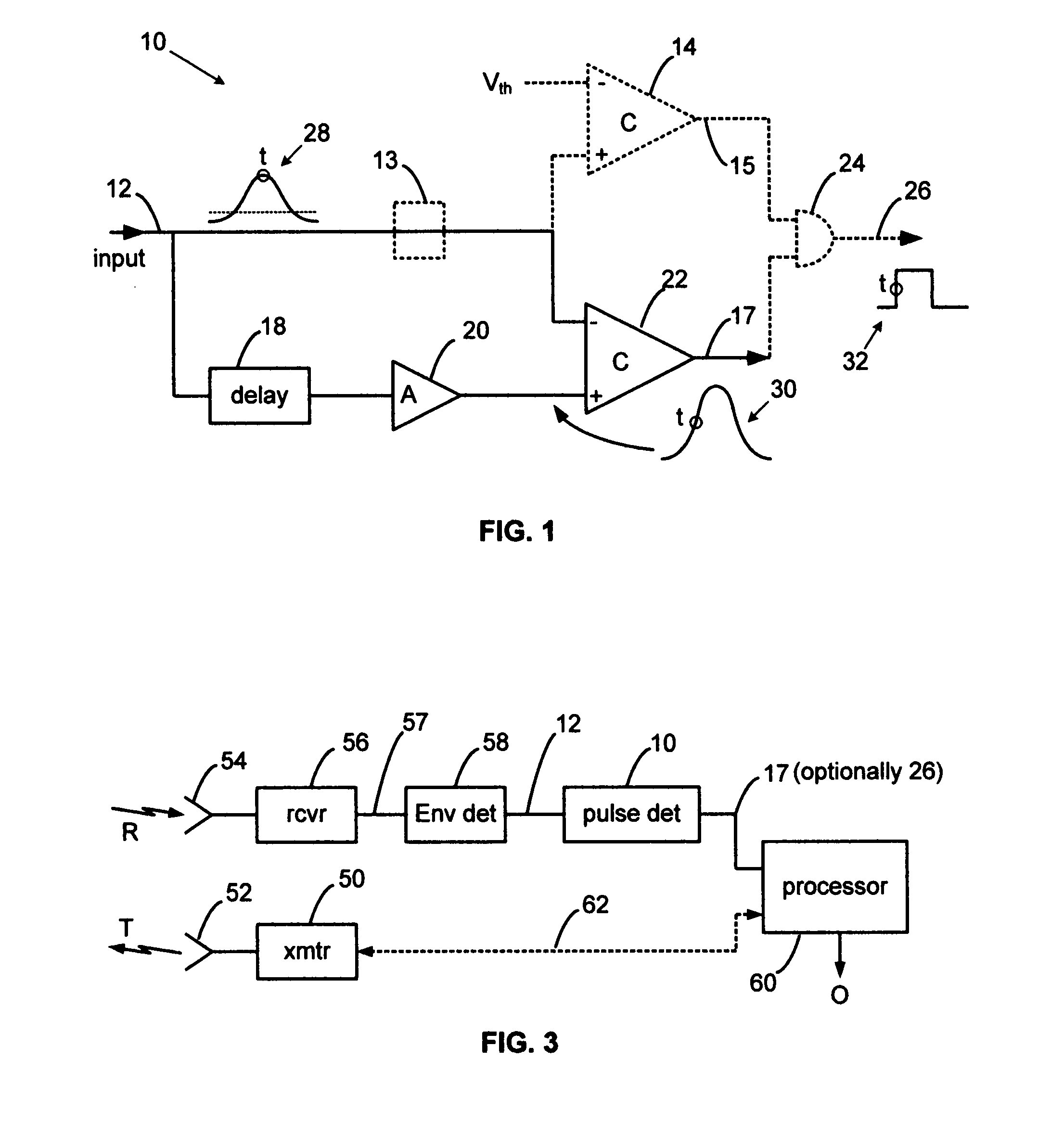
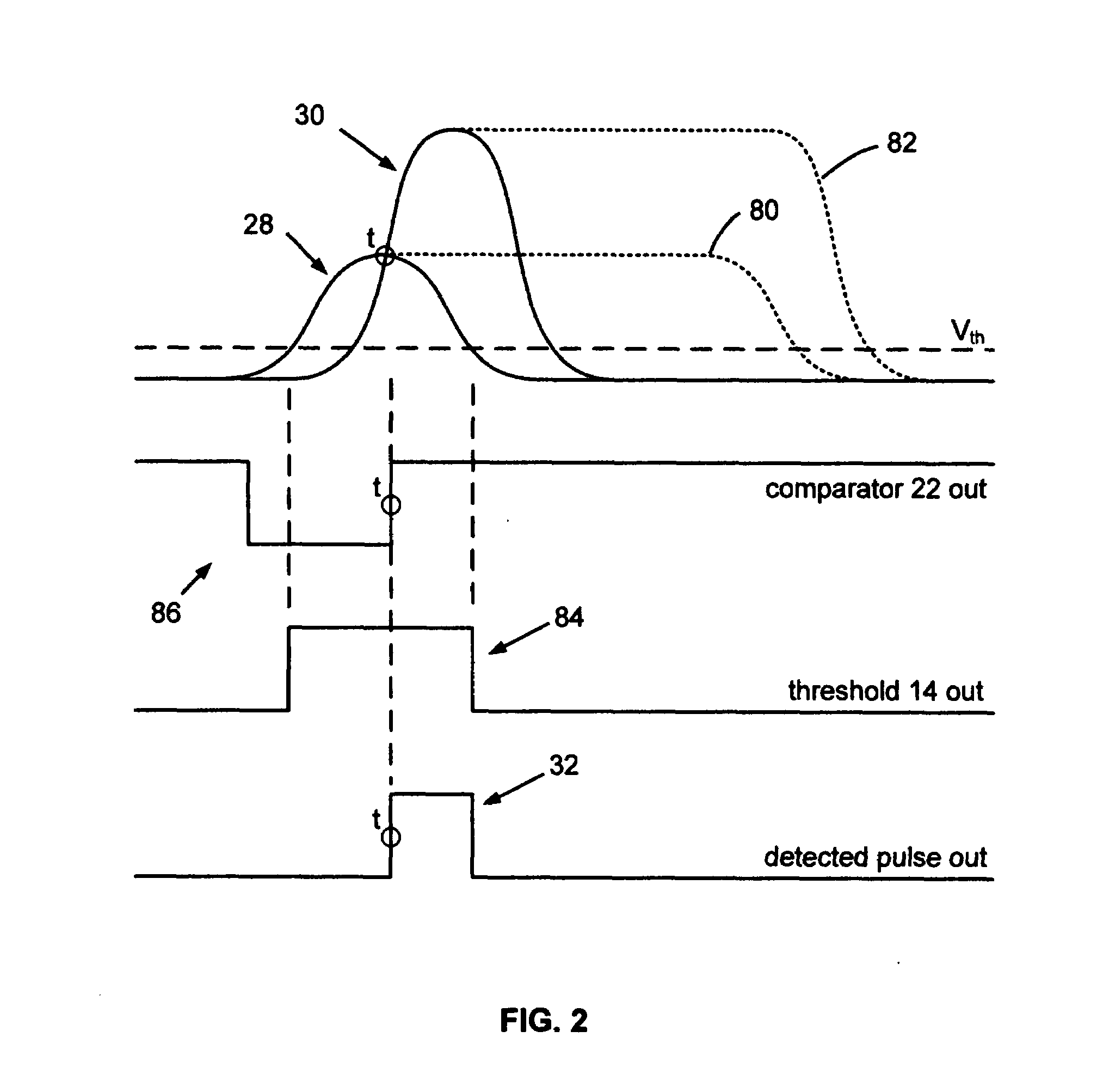
[0015]The present invention overcomes the limitations of prior radar video pulse (RVP) detectors by using the RVP itself as an automatic reference voltage. A delayed and amplified version of the RVP is then used as the pulse to be detected. Detection occurs whenever the delayed and amplified RVP exceeds the instantaneous amplitude of the RVP itself. Since the detection reference is set by the RVP itself, i.e., since it is self-referencing, the temporal location of the detection point is independent of the RVP amplitude.

[0016]The temporal location of the detection point is effectively on the leading edge of the RVP, generally in the middle of the risetime where the slew rate is greatest. Accordingly, sensitivity to noise is minimized, particularly wh...


PUM


Abstract

An automatic pulse detector compares a radar video pulse to a delayed and amplified version of itself. The radar video pulse serves as an amplitude reference for a comparator. A delayed and amplified version of the same pulse serves as the pulse to be detected. Time of detection is amplitude independent and is not degraded by flat-topped pulses. Pulse detection occurs at a fixed, fractional point on the leading edge of a pulse where noise has less temporal influence than at the top of a pulse. Unlike a time-of-peak detector, the self-referencing pulse detector is well-suited to detecting wide, flat-topped pulses produced by expanded-time, pulse-echo radars operating in relatively narrow ISM bands.

Description

BACKGROUND OF THE INVENTION[0001]1. Field of the Invention[0002]The present invention relates to radar detection circuits and more particularly to automatic pulse detection circuits. The invention can be used to detect pulses for wideband and UWB radar rangefinders, time domain reflectometers and radiolocation systems.[0003]2. Description of Related Art[0004]Radar echo pulses exhibit large amplitude variations, depending on target size, range and dielectric constant, and these variations produce range measurement errors when the pulses are detected with a fixed threshold detector. Echo amplitude variations also occur to a lesser extent with TDR-based tank level sensors, mainly being limited to dielectric constant variations of the liquid in the tank. However, accurate TDR-based tank level sensors require accurate, amplitude-independent pulse detectors.[0005]Detectors with amplitude-tracking thresholds or other means to achieve amplitude independence are generally termed automatic pu...

Claims


Application Information

Patent Timeline
IPC IPC(8): G01S13/00
CPCG01S7/285H04K3/822G01S13/0209
Inventor MCEWAN, THOMAS EDWARD
Owner MCEWAN TECH
Why Eureka
Try Eureka