
Method and apparatus for an efficient framework for testcell development

a testcell and framework technology, applied in the field of automatic test equipment, can solve the problems of inefficiency of prior methods of developing applications and/or process control methods to program ate assemblies, hinder the integration of existing customer frameworks, and considerable inefficiency in the field, so as to improve the efficiency of production application development, minimize dependencies, and minimize dependencies

Active Publication Date: 2019-08-06
ADVANTEST CORP
View PDF34 Cites 0 Cited by
  • Summary
  • Abstract
  • Description
  • Claims
  • Application Information

AI Technical Summary

Benefits of technology

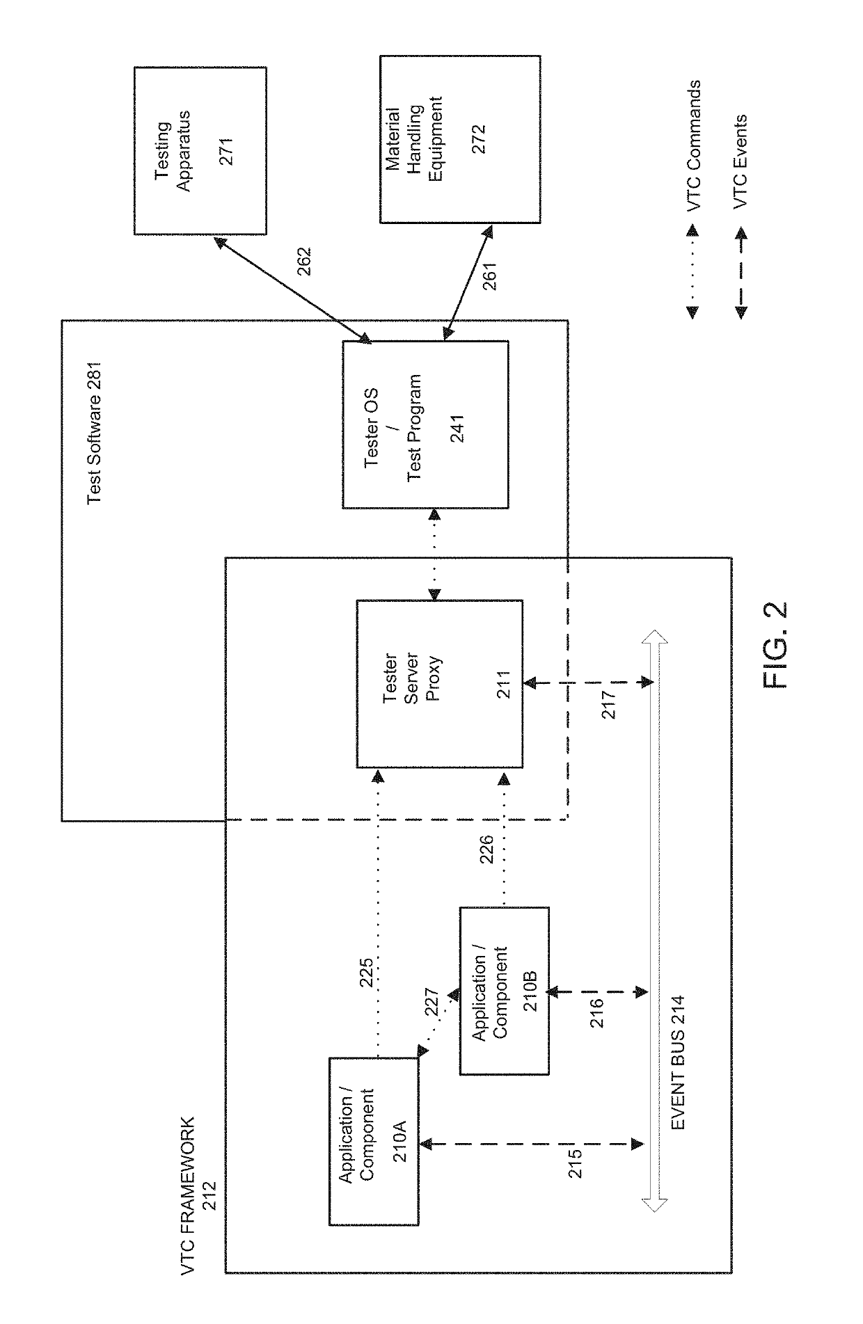
The present invention provides a test framework that is efficient, performance oriented, and minimizes dependencies. This improves the efficiency of production application development and allows test process control methods or applications to be easily integrated into different versions and revisions of the test software. The interface between components is more straightforward and efficient, allowing for rapid prototyping and development. The test framework also allows software component interfaces to be decoupled and for the components to communicate with each other efficiently and with near zero latency. Overall, embodiments of the present invention advantageously minimizes dependencies, resulting in lower complexity for field application engineers.

Problems solved by technology

Prior methods of developing the applications and / or process control methods to program ATE assemblies have been inefficient because the interfaces to configure the process control methods have been tightly coupled to the manufacturing process.
Further, these dependencies hindered the integration of existing customer frameworks.
The man-hours spent in the customization process resulted in considerable inefficiencies in the field.
Additionally, the various versions of the test software made providing support to the customers difficult and inefficient for the field engineers and manufacturers of test equipment.
Prior developers of ATE hardware and software have attempted to decouple interfaces from manufacturing processes with limited success.
Attempts to decouple the interfaces have incurred a cost of complexity that limits usability and acceptance.
Further, prior solutions have incurred run time costs that are a critical disadvantage during the test cycle.

Method used


Image

  • Method and apparatus for an efficient framework for testcell development
  • Method and apparatus for an efficient framework for testcell development
  • Method and apparatus for an efficient framework for testcell development

Examples


Embodiment Construction

[0022]Reference will now be made in detail to the preferred embodiments of the present invention, examples of which are illustrated in the accompanying drawings. While the invention will be described in conjunction with the preferred embodiments, it will be understood that they are not intended to limit the invention to these embodiments. On the contrary, the invention is intended to cover alternatives, modifications and equivalents, which may be included within the spirit and scope of the invention as defined by the appended claims. Furthermore, in the following detailed description of embodiments of the present invention, numerous specific details are set forth in order to provide a thorough understanding of the present invention. However, it will be recognized by one of ordinary skill in the art that the present invention may be practiced without these specific details. In other instances, well-known methods, procedures, components, and circuits have not been described in detail ...


PUM


Abstract

A method of performing a test using automated test equipment (ATE) is disclosed. The method comprises configuring a proxy application programming interface (API) services module, wherein the proxy API services module provides an interface between a test framework and a test software environment, wherein the test framework communicates with the test software environment though the proxy API services module, wherein the test software environment is communicatively coupled with test hardware, and wherein the proxy API services module is configured to isolate the test framework from dependencies associated with the test software environment. The method further comprises communicating commands synchronously between the test framework and the test software environment, wherein the test framework comprises a plurality of components, and wherein the plurality of components is operable to receive commands from the test software environment and further operable to transmit commands to the test software environment through the proxy API services module.

Description

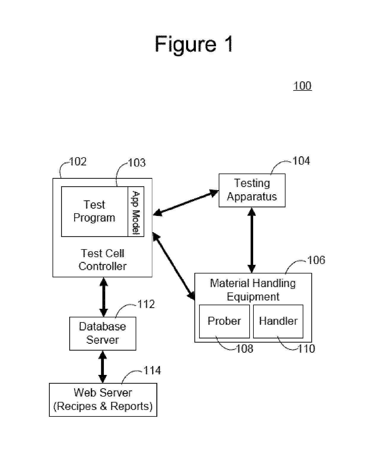
CROSS REFERENCE TO RELATED APPLICATIONS[0001]This application claims priority from and is a continuation-in-part of co-pending U.S. patent application Ser. No. 13 / 444,705, “Creation and Scheduling of a Decision and Execution Tree of a Test Cell Controller,”, Henry Arnold, filed Apr. 11, 2012, the entire disclosure of which is incorporated herein by reference.TECHNICAL FIELD[0002]The present disclosure relates generally to the field of automated test equipment and more specifically to the field of process control of automated test equipment.BACKGROUND[0003]Automated test equipment (ATE) can be any testing assembly that performs a test on a device, semiconductor wafer or die, etc. ATE assemblies may be used to execute automated tests that quickly perform measurements and generate test results that can then be analyzed. An ATE assembly may be anything from a computer system coupled to a meter, to a complicated automated test assembly that may include a custom, dedicated computer contro...

Claims


Application Information

Patent Timeline
Patent Type & Authority Patents(United States)
IPC IPC(8): G01R31/28
CPCG01R31/2834G01R31/2894
Inventor BURAS, BRIAN
Owner ADVANTEST CORP
Learn More