
Electrical equipment room temperature control system for oil exploration

A technology for electrical equipment and temperature control systems, applied in the direction of control/regulation systems, temperature control, non-electric variable control, etc., can solve problems such as reducing the practicality of control, affecting the normal operation of equipment, and reducing the reliability of temperature control systems, etc., to achieve Improve reliability and practicability, zero delay, and improve reliability

Inactive Publication Date: 2017-01-04
建宇(上海)石油科技有限公司
View PDF9 Cites 0 Cited by
  • Summary
  • Abstract
  • Description
  • Claims
  • Application Information

AI Technical Summary

Problems solved by technology

[0004] In the existing temperature control system, many fans are used to dissipate heat, but after long-term work, the air outlet of the fan will accumulate a lot of dust at the air outlet due to frictional electricity generation, and the dust will enter the equipment after accumulation Internally, it affects the normal operation of the equipment and reduces the reliability of the temperature control system; not only that, when controlling the temperature control system, it is controlled by communication, but because the existing communication circuit control has a delay , thereby reducing the practicality of the control

Method used


Image

  • Electrical equipment room temperature control system for oil exploration
  • Electrical equipment room temperature control system for oil exploration
  • Electrical equipment room temperature control system for oil exploration

Examples


Embodiment Construction

[0025] The present invention is described in further detail now in conjunction with accompanying drawing. These drawings are all simplified schematic diagrams, which only illustrate the basic structure of the present invention in a schematic manner, so they only show the configurations related to the present invention.

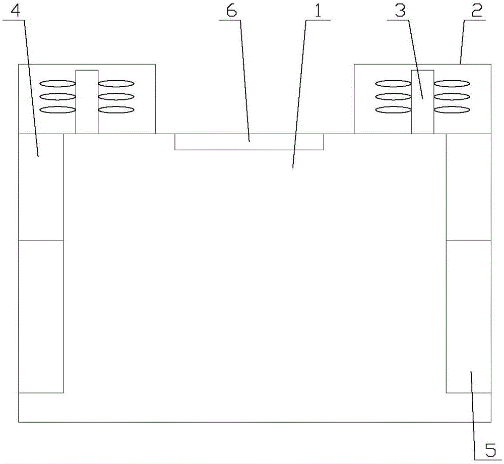
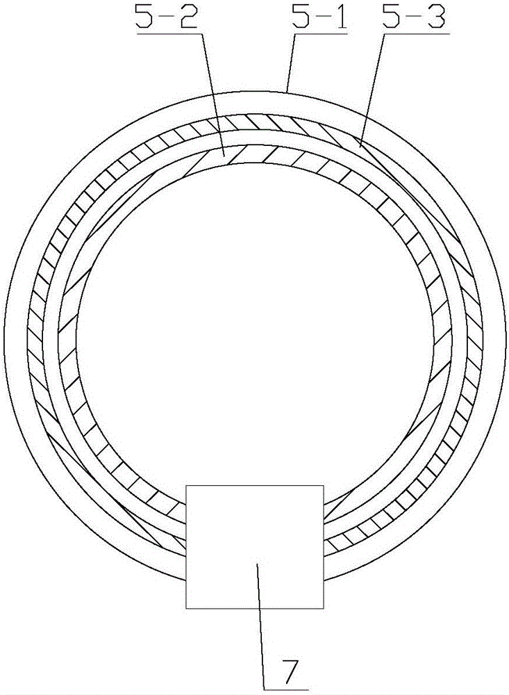
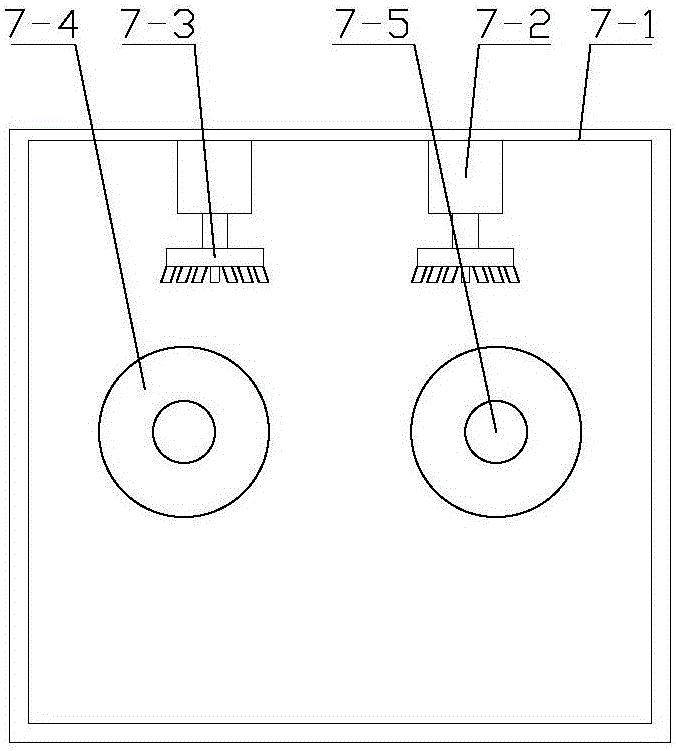
[0026] Such as Figure 1-Figure 4 As shown, a temperature control system for an electrical equipment room for oil exploration includes an equipment room 1, a temperature control mechanism and a central control device arranged inside the equipment room 1, and the temperature control mechanism is electrically connected to the central control device;

[0027] The temperature control mechanism includes an air outlet 6 and two temperature control assemblies respectively arranged on both sides of the equipment room 1, and the temperature control assembly includes an air inlet 2, a ventilation pipe 4 and an air outlet pipe 5 arranged at the top of the equipment room ...


PUM


Abstract

The invention relates to an electrical equipment room temperature control system for oil exploration. The electrical equipment room temperature control system comprises an equipment room, a temperature control mechanism and a central control device. The temperature control mechanism is electrically connected with the central control device, and comprises an air outlet and two temperature control components respectively arranged on two sides of the equipment room; each temperature control component comprises air inlets, a breather pipe and an air outlet pipe which are arranged at the top end of the equipment room; each air inlet communicates with each air outlet pipe through each breather pipe; the air outlet is formed in the midpoint of the top part of the equipment room. According to the electrical equipment room temperature control system for oil exploration, a drive shaft drives a drive wheel to rotate and move on a pipe body, meanwhile, and a rotary motor drives a cleaning brush to rotate to collect dust on the inner wall of the pipe body, so that the reliability of the temperature control system is improved; besides, in a communication circuit, through changing parameters of a third resistor and a capacitor, the zero time delay of the communication circuit can be realized, so that the reliability and the practicability of the temperature control system are improved.

Description

technical field [0001] The invention relates to a temperature control system for electrical equipment used in oil exploration. Background technique [0002] The so-called oil exploration is to find and ascertain oil and gas resources, and use various exploration methods to understand the underground geological conditions, understand the conditions of oil generation, oil storage, oil and gas migration, accumulation, preservation, etc., comprehensively evaluate oil and gas prospects, and determine oil and gas resources. Gather favorable areas, find traps for oil and gas storage, ascertain the area of ​​oil and gas fields, find out the situation of oil and gas layers and the process of production capacity, and increase crude oil reserves and related oil and gas products for the country. [0003] When conducting oil exploration, some mechanical and electronic equipment is needed to ensure its normal operation, so it is necessary to place these mechanical and electronic equipment...

Claims


Application Information

Patent Timeline
IPC IPC(8): G05D23/20
CPCG05D23/20
Inventor 曹燕红
Owner 建宇(上海)石油科技有限公司
Learn More