Camshaft lobe and method of making same

a camshaft and lobe technology, applied in the field of camshaft lobe manufacturing, can solve the problems of inconvenient use of conventional manufacturing methods, inability to tailor a particular material's desirable properties, heavy load, and inability to meet the requirements of the application, and achieves superior properties, high load, and wear.

Inactive Publication Date: 2010-04-08
GM GLOBAL TECH OPERATIONS LLC
View PDF19 Cites 10 Cited by
  • Summary
  • Abstract
  • Description
  • Claims
  • Application Information

AI Technical Summary

Benefits of technology

[0006]In another option, instead of a powder, the second material may be in the form of a substantially rigid insert. Such insert may be made from a different material from the alloy used to make up the remainder of the component. In one form, the different material may be a hardenable steel alloy, ceramic material or other long-wearing, high load-bearing composition. Such an insert defines a profile such that can be placed over at least a portion of the first material such that the second material forms an outer surface of a part of the component that is expected to be exposed to higher levels of load, wear, friction or the like. For example, in situations where the component includes an eccentricity or related non-axisymmetric shape and such non-axisymmetric shape corresponds to the part of the component in need of additional structural properties, the second material can be placed in such a way that it makes up at least a majority of the non-axisymmetric exterior profile, or takes a majority of the loading when the load is at a maximum. The substantially rigid insert may be made from either a reusable or non-reusable. In the case of the latter, the insert may remain with the formed component upon completion of the compaction. In the case of the former, such as when being used to shape the outer profile of the component of interest, the insert does not remain with the automotive engine component upon the fabrication such that it may be re-used. In one configuration, during the forming process, the one or more substantially rigid insert cooperates with one or more reusable inserts such that an outer shape of the component is defined by such cooperation. In a more particular form, numerous such reusable segments can be placed within a die so that their inner surfaces compact the first and second materials in response to the DMC process. In this way, the reusable segments can press the non-reusable segments into place in a particular location in the component to be formed.
[0007]According to another aspect of the invention, a method of fabricating a camshaft lobe is disclosed. The method includes providing a die with an interior profile that substantially defines an exterior surface of the lobe, placing a first material within a first part of the interior profile of the die, placing a second material within a second part of the interior profile of the die such that the second material is used to form at least a portion of the exterior surface of the lobe that corresponds to the lobe eccentricity, and forming the lobe using dynamic magnetic compaction. As with the previous aspect, one significant advantage over the prior art DMC process is that non-axisymmetric and related irregular component shapes can be formed.
[0008]Optionally, the second material occupies a majority of the exterior surface of the lobe that corresponds to the lobe eccentricity. In this way, the use of materials with tribologically superior properties can be tailored to corresponding surface regions of the lobe. This can be an advantageous way of supplementing the tribological or related structural properties of heavily-loaded parts of the lobe, such as its eccentric region, where conventional DMC may not be capable of producing a part with the necessary structural attributes. In another option, at least one of the first and second materials is made of a powder that can be compacted via the DMC process. In a further option, the second material can be made from a different composition than the first material. In this way, metal alloys, ceramic precursors or related materials can be strategically placed on portions of the exterior surface of the lobe to tailor the material properties to the load-bearing needs of the lobe. In yet another option, the second material is made from a substantially rigid non-reusable insert that may be operated upon by a reusable insert. The interior profile of the die used to form the lobe may be made up of reusable inserts that cooperate with the one or more non-reusable inserts so that the second material that makes up the non-reusable insert is pressed together with the first material. In this way, the lobe is formed as a substantially unitary structure that can be further processed.

Problems solved by technology

The use of conventional manufacturing processes, such as casting, forging or the like, tends to produce components which, while satisfactory from a load-bearing perspective, result in heavy, inefficient structures.
Likewise, the use of conventional manufacturing approaches is not conducive to tailoring a particular material's desirable properties to discreet locations on a camshaft lobe.
Because such more robust materials may involve greater expense, weight or detrimental features, they may only be used sparingly.

Method used


Image

  • Camshaft lobe and method of making same
  • Camshaft lobe and method of making same
  • Camshaft lobe and method of making same

Examples


Embodiment Construction

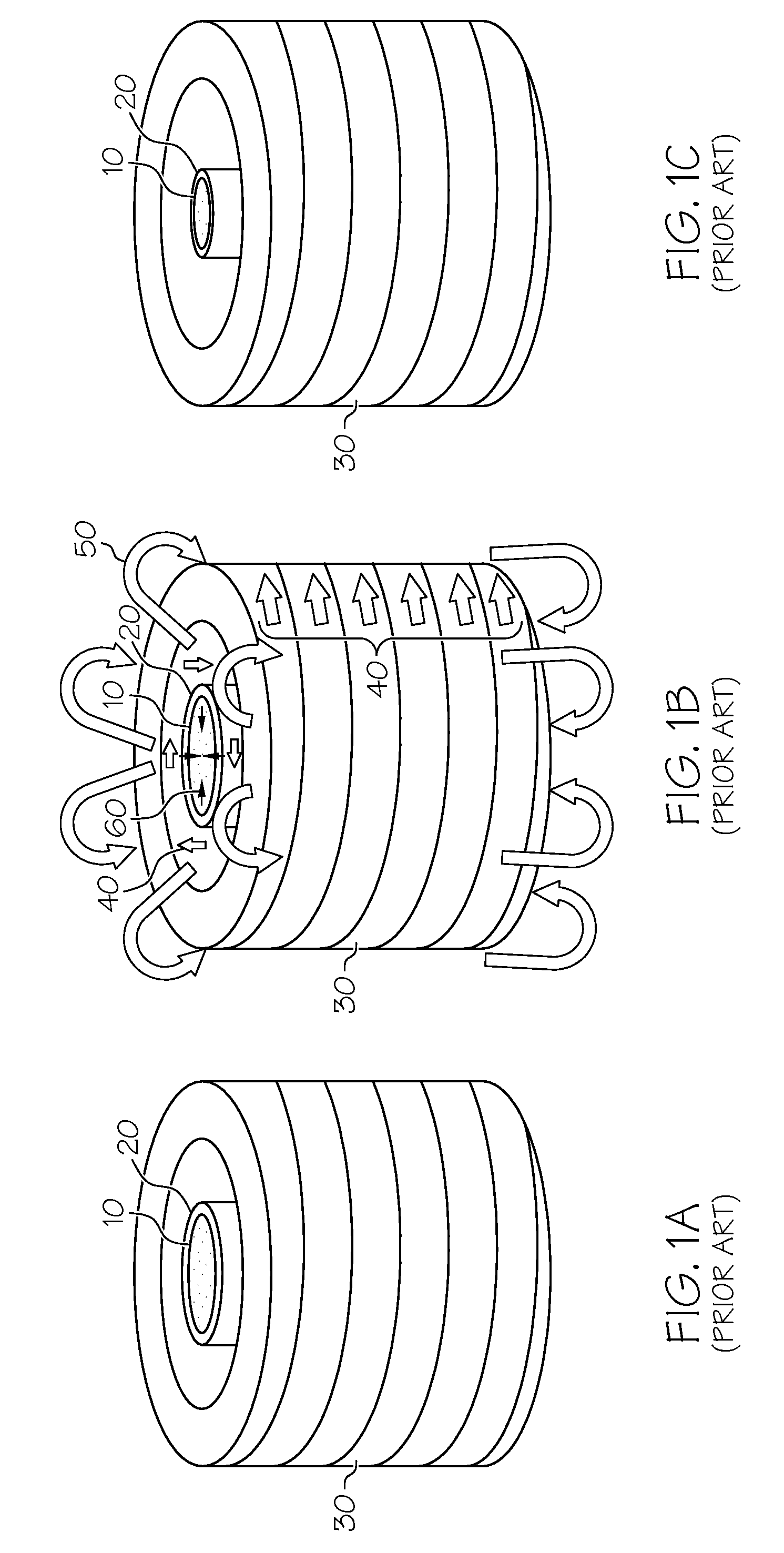
[0018]Referring initially to FIGS. 1A through 1C, the DMC process according to the prior art is shown, where a generally cylindrical-shaped component is produced. FIG. 1A shows a powder material 10 placed within an electrically conductive cylindrical armature 20. A coil 30 is connected to a direct current power supply (not shown) such that electric current can be passed through the coil 30. The powder material 10 substantially fills the electrically conductive armature 20 (also called a sleeve). Referring with particularity to FIG. 1B, a large quantity of electrical current 40 is made to flow through the coil 30; this current induces a magnetic field 50 in a normal direction that in turn sets up magnetic pressure pulse 60 that is applied to the electrically conductive container 20. This radially inward pressure acts to compress the container 20, causing the powder material 10 to become compacted and densified into a full density parts in a very brief amount of time (for example, les...


PUM

PropertyMeasurementUnit
voltageaaaaaaaaaa
tribological propertiesaaaaaaaaaa
shapeaaaaaaaaaa

Abstract

An automotive engine component and method of producing the same. The method uses dynamic magnetic compaction to form components with non-axisymmetric and related irregular shapes. A die is used that has an interior profile that is substantially similar to the non-axisymmetric exterior of the component to be formed such that first and second materials can be placed into the die prior to compaction. The first material is in powder form and can be placed in the die to make up a first portion of the component being formed, while a second material can be placed in the die to make up a second portion of the component. The second material, which may possess different tribological properties from those of the first material, can be arranged in the die so that upon formation, at least a portion of the component's non-axisymmetric exterior profile is shaped by or includes the second material.

Description

BACKGROUND OF THE INVENTION[0001]The present invention relates generally to the manufacture of automotive engine components possessing non-round exterior shapes using a powder metallurgy process, and more particularly to the manufacture of camshaft lobes using a modified dynamic magnetic compaction (DMC) process.[0002]Automotive engine camshaft lobes must endure significant and repeated mechanical loading under high-speed, high-temperature and tribologically-varying conditions. The use of conventional manufacturing processes, such as casting, forging or the like, tends to produce components which, while satisfactory from a load-bearing perspective, result in heavy, inefficient structures. Likewise, the use of conventional manufacturing approaches is not conducive to tailoring a particular material's desirable properties to discreet locations on a camshaft lobe. Furthermore, the use of DMC, which is taught in U.S. Pat. Nos. 5,405,574, 5,611,139, 5,611,230 and 5,689,797 (all of which ...

Claims


Application Information

Patent Timeline
Patent Type & Authority Applications(United States)
IPC IPC(8): B21D53/84
CPCB22F3/087B22F5/008B22F5/106B22F7/06Y10T29/49293B22F2999/00B22F2202/05
Inventor WAKADE, SHEKHAR G.ROZARIO, FREDERICK J.CLEVER, GLENN E.ROBBINS, JOSEPH E.KORNBLUM, STEPHEN R.
Owner GM GLOBAL TECH OPERATIONS LLC
Why Eureka
Try Eureka