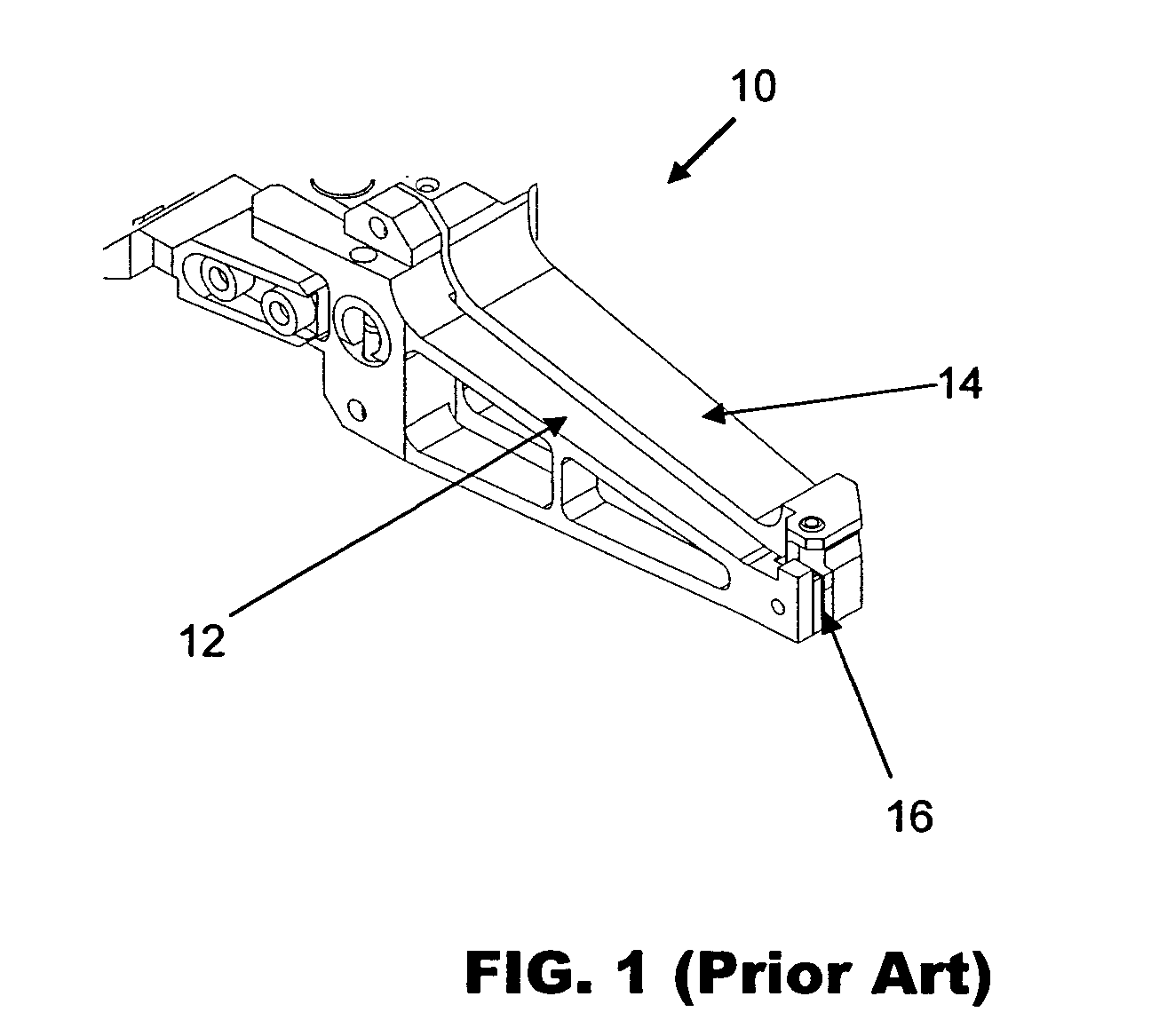
Wire clamping plate

Active Publication Date: 2006-07-13
ASM ASSEMBLEY AUTOMATION LTD
View PDF3 Cites 1 Cited by
  • Summary
  • Abstract
  • Description
  • Claims
  • Application Information

AI Technical Summary

Benefits of technology

[0011] It is therefore an object of the invention to seek to provide a material for manufacturing wire clamping plates for wire clamps that exhibits electrical conductivity and a high level of wear resistance.

Problems solved by technology

The friction created between the wire and the clamping plates, especially due to the force arising from clamping and pulling the wire for breaking the wire, causes wearing-out at the surfaces of the clamping plates.
This wearing-out at the surfaces of the clamping plates affects the wire looping consistency and other related performances.
Even so, when these alloys are used in wire clamping plates, wear marks on the clamping plates can be observed after a certain number of wire bonding cycles.
It has been observed that wear usually starts from the alloys' soft binder phase, at or adjacent to the interphase boundaries between the hard phase and soft binder phase.
In this condition, the grain is susceptible to detachment from the bonded matrix.
When the bonding wire is gold wire and the binder is cobalt, the situation is even worse because gold wire tends to stick to cobalt, causing even faster wearing out of the clamping plates.
It is thus widely accepted that a key disadvantage of using cemented carbides for wire clamping plates is the existence of the aforesaid soft binder phase.
Nonetheless, it is not easy to avoid the binder phase because it is used to enhance the material integrity, in particular its strength.
Moreover, it is difficult to manufacture binderless carbides free of porosity.
Porosity also deteriorates the wear resistance of the wire clamping plate.

Method used


Image

  • Wire clamping plate

Examples


Embodiment Construction

[0015] An example of a material that is suitable for manufacturing a wire clamping plate according to the preferred embodiment of the invention will now be described. Based on the aforementioned considerations, it is proposed that a single phase, hard and electrically conductive material be used for making the wire clamping plates. In this respect, the material used according to the preferred embodiment of the invention is a doped silicon carbide (SiC) material. The silicon carbide material may be in single crystal or poly-crystal form.

[0016] Generally, a commercially-available SiC crystal may be utilized. SiC is one of the hardest commercially-available materials with a Mohr's hardness index of 9, just next to that of diamond (10). The SiC is doped with a doping element or dopant, preferably aluminum (Al) (p-type semiconductor) or nitrogen (N) (n-type semiconductor), so that it can conduct electricity with introduced charge carriers, namely free electrons or holes.

[0017] Single c...


PUM

PropertyMeasurementUnit
Lengthaaaaaaaaaa
Forceaaaaaaaaaa
Electrical conductivityaaaaaaaaaa

Abstract

A wire clamping plate is provided for a wire clamp that is adapted to contact a length of metallic wire when the wire clamp is applying a clamping force on the wire. The wire clamping plate comprises doped silicon carbide, which makes it electrically conductive and exhibit a high level of wear resistance.

Description

FIELD OF THE INVENTION [0001] The invention relates to a wire clamp, and in particular to the wire clamping plates of a wire clamp, which is used for gripping and controlling metallic bonding wire during wire bonding operations. BACKGROUND AND PRIOR ART [0002] Wire bonding and bumping are important steps in electronic packaging. Wire bonding involves the connection of conductive wires between different electronic components of a semiconductor device, usually a semiconductor chip and a carrier or substrate, such as a lead frame. Bumping involves the placement of solder balls on a wafer or semiconductor chip, to enable electrical connections to be made between the chip and another electronic component. [0003] To plant a bump or bond a wire onto a metallic connection pad either on a chip or a chip-mounting substrate by using a wire bonder, an effective bond or connection may be made between a bonding wire (which is typically made of gold, aluminum or copper) and the connection pad from...

Claims


Application Information

Patent Timeline
IPC IPC(8): B23K37/00
CPCB23K20/004B23K2201/32H01L24/45H01L2224/45124H01L2224/45144H01L2224/45147H01L2224/78H01L2224/85H01L2924/01005H01L2924/01007H01L2924/01013H01L2924/01014H01L2924/01015H01L2924/01027H01L2924/01028H01L2924/01029H01L2924/01047H01L2924/01074H01L2924/01079H01L2924/01082H01L2924/00014H01L24/78H01L2924/01033H01L2924/01041H01L2924/014H01L2924/10253H01L2924/00H01L2224/48B23K2101/32
Inventor LIU, DEMINGFU, RAN
Owner ASM ASSEMBLEY AUTOMATION LTD
Why Eureka
Try Eureka