Consumable Downhole Tools

a downhole tool and consumable technology, applied in the direction of fluid removal, borehole/well accessories, insulation, etc., can solve the problems of inconsistent yield, time-consuming and expensive operation of milling and drilling, etc., and achieve the effect of reducing the structural integrity of the downhole tool

Active Publication Date: 2010-04-29
MCR OIL TOOLS +1
View PDF104 Cites 115 Cited by
  • Summary
  • Abstract
  • Description
  • Claims
  • Application Information

AI Technical Summary

Problems solved by technology

Nevertheless, milling and drilling continues to be a time consuming and expensive operation.
This method, however, sometimes yields inconsistent results.

Method used


Image

  • Consumable Downhole Tools
  • Consumable Downhole Tools
  • Consumable Downhole Tools

Examples


Embodiment Construction

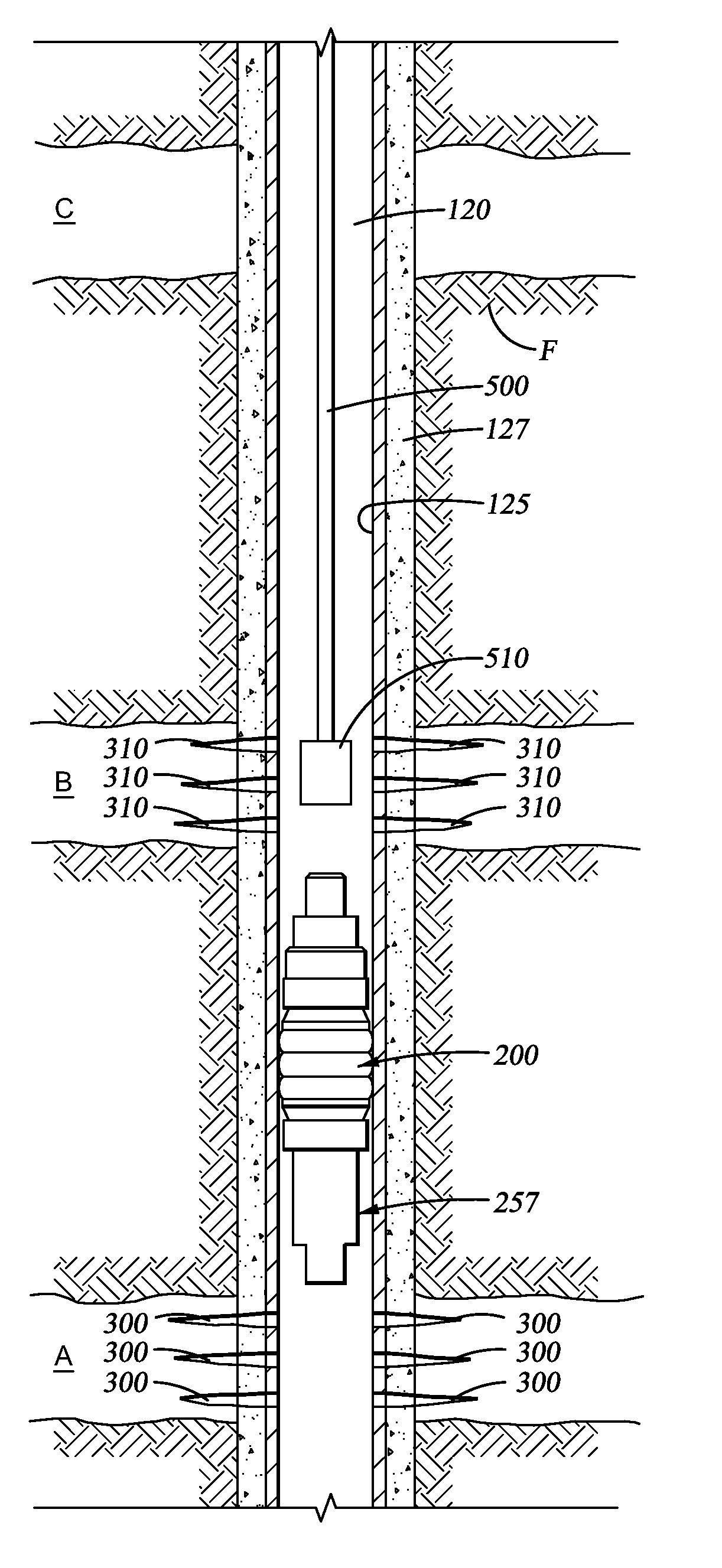
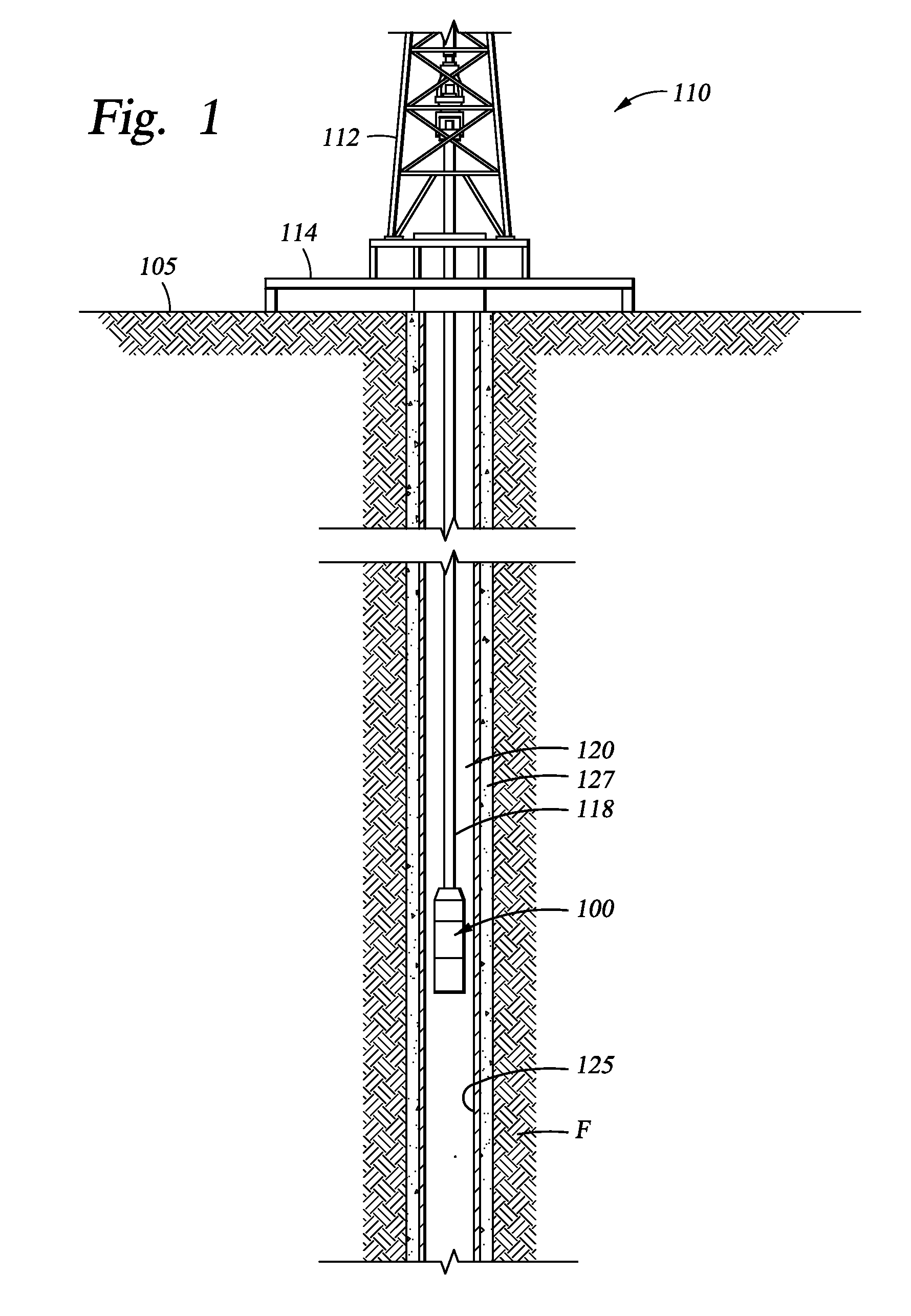
[0016]FIG. 1 schematically depicts an exemplary operating environment for a consumable downhole tool 100. As depicted, a drilling rig 110 is positioned on the earth's surface 105 and extends over and around a well bore 120 that penetrates a subterranean formation F for the purpose of recovering hydrocarbons. At least the upper portion of the well bore 120 may be lined with casing 125 that is cemented 127 into position against the formation F in a conventional manner. The drilling rig 110 includes a derrick 112 with a rig floor 114 through which a work string 118, such as a cable, wireline, E-line, Z-line, jointed pipe, or coiled tubing, for example, extends downwardly from the drilling rig 110 into the well bore 120. The work string 118 suspends a representative consumable downhole tool 100, which may comprise a frac plug, a bridge plug, a packer, or another type of well bore zonal isolation device, for example, as it is being lowered to a predetermined depth within the well bore 12...


PUM


Abstract

A method of removing a downhole tool from a wellbore comprising contacting the tool with a heat source wherein the tool comprises at least one load-bearing component comprising a thermally degradable material. A method of reducing the structural integrity of a downhole tool comprising fabricating the load-bearing components of the tool from a thermally degradable material. A method of removing a downhole tool comprising mechanically milling and / or drilling the tool from a wellbore wherein the tool comprises at least one load bearing component comprising a phenolic resin wherein the phenolic resin comprises a rosole, a novalac or combinations thereof.

Description

CROSS-REFERENCE TO RELATED APPLICATIONS[0001]This application is a continuation of U.S. patent application Ser. No. 11 / 677,755, filed Feb. 22, 2007 by Robert Preston Clayton, et al., now published as U.S. 2008 / 0202764 A1, and entitled “Consumable Downhole Tools,” which is incorporated herein by reference as if reproduced in its entirety. This application is also related to commonly owned U.S. patent application Ser. No. 11 / 423,076, now published as U.S. 2007 / 0284097 A1, and entitled “Consumable Downhole Tools,” U.S. patent application Ser. No. 11 / 423,081, now published as U.S. 2007 / 0284114 A1 entitled “Method for Removing a Consumable Downhole Tool,” both filed on Jun. 8, 2006, and U.S. patent application Ser. No. 12 / 639,567, entitled “Consumable Downhole Tools” and filed on Dec. 16, 2009, each of which is incorporated by reference herein in its entirety.STATEMENT REGARDING FEDERALLY SPONSORED RESEARCH OR DEVELOPMENT[0002]Not applicable.REFERENCE TO A MICROFICHE APPENDIX[0003]Not ap...

Claims


Application Information

Patent Timeline
Patent Type & Authority Applications(United States)
IPC IPC(8): E21B29/00
CPCE21B29/02
Inventor CLAYTON, ROBERTBERSCHEIDT, KEVIN
Owner MCR OIL TOOLS
Why Eureka
Try Eureka