
Eureka
For R&D, Eureka makes reading and utilizing patents & technical documents easy.
Eureka AIR
Designed for self-driven R&D workflows. Generate viable solutions, solve complex R&D challenges, empower your innovation with AI.

Eureka Materials
Designed for material experts only. Revolutionize your material R&D, from search, analyze, to developing new materials.

TechResearch
Generate reliable direction feasibility study reports for your R&D in just a few steps.

TechSeek
Discover and master advanced knowledge NOW. Basics, ideas, possibilities, all at once.

TechMind
As an expert in R&D Theories, TechMind can generates customized viable solutions instantly.

TechRisk
Analyze your overall solution with one click, know your potential R&D risks in advance.

TechMonitor
Get weekly tech updates, stay abreast of the latest tech innovations and key insights.
Horizontal electric field type liquid crystal display device
- Summary
- Abstract
- Description
- Claims
- Application Information
AI Technical Summary
Benefits of technology
Problems solved by technology
Method used
Image

Examples
first embodiment
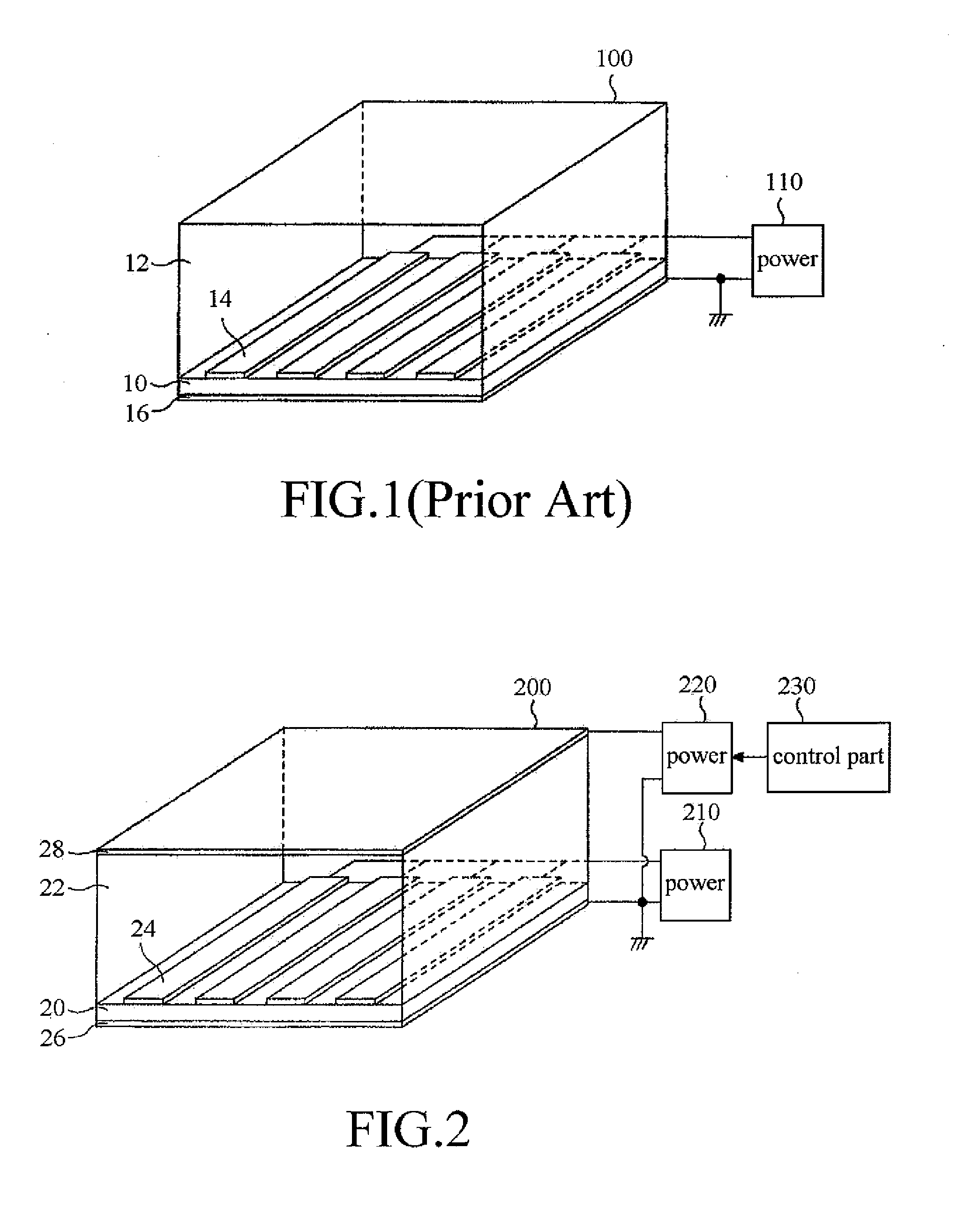
[0022]FIG. 2 is a pixel structure of a horizontal electric field type liquid crystal display device in accordance with the present invention.
[0023]The pixel 200 shown in FIG. 2 includes a viewing angle adjusting electrode 28 as well as a substrate 20, liquid crystal layer 22, pixel electrodes 24, and common electrode 26. The viewing angle adjusting electrode 28 and the substrate 20 are arranged to oppose to each other and sandwich the liquid crystal layer 22. The viewing angle adjusting electrode 28, for example, can be a transparent electrode made of indium tin oxide.
[0024]The pixel electrode 24 and the common electrode 26 are electrically coupled to a first power 210. An electric potential difference is generated between the pixel electrode 24 and the common electrode 26 when turning the power 210 on. Due to the electric potential difference, a horizontal electric field is generated in the liquid crystal layer 22. Accordingly, the orientation of liquid crystal molecules (not shown...
second embodiment
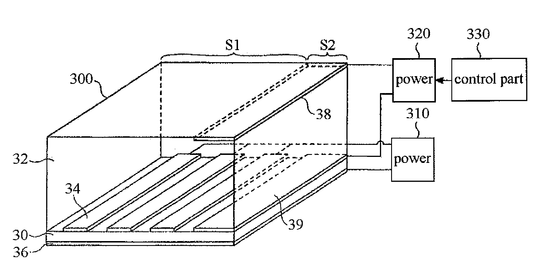
[0036]FIG. 5 is a pixel structure of a horizontal electric field type liquid crystal display device in accordance with the present invention.
[0037]A pixel 300 shown in FIG. 5 includes a first sub-pixel S1 and a second sub-pixel S2. The first sub-pixel S1 is used for normal display while the second sub-pixel S2 is used for adjusting the viewing angle only.
[0038]The first sub-pixel S1 and the second sub-pixel S2 share a substrate 30, a liquid crystal layer 32, and a common electrode 36. The first sub-pixel S1 further includes pixel electrodes 34 having a certain width that are parallel to each other at a regular interval on the substrate 30. The second sub-pixel S2 further includes a first viewing angle adjusting electrode 38 and a second viewing angle adjusting electrode 39. The first viewing angle adjusting electrode 38 and the substrate 30 are opposed to each other, sandwiching the liquid crystal layer 32. The second viewing angle adjusting electrode 39 is disposed on the substrate...
PUM
 Abstract
Description
Claims
Application Information
 - R&D Engineer
- R&D Manager
- IP Professional
- Industry Leading Data Capabilities
- Powerful AI technology
- Patent DNA Extraction
Browse by: Latest US Patents, China's latest patents, Technical Efficacy Thesaurus, Application Domain, Technology Topic, Popular Technical Reports.
© 2024 PatSnap. All rights reserved.Legal|Privacy policy|Modern Slavery Act Transparency Statement|Sitemap|About US| Contact US: help@patsnap.com