

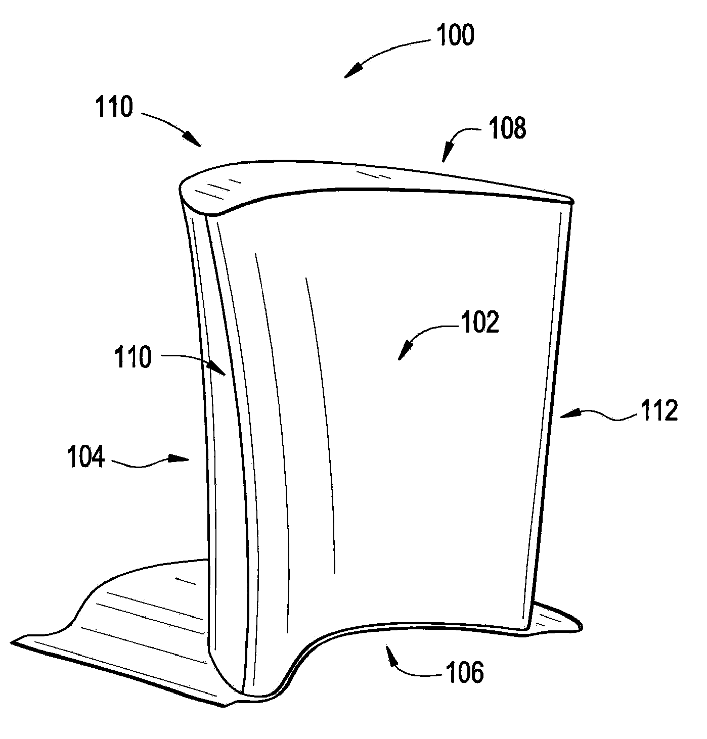
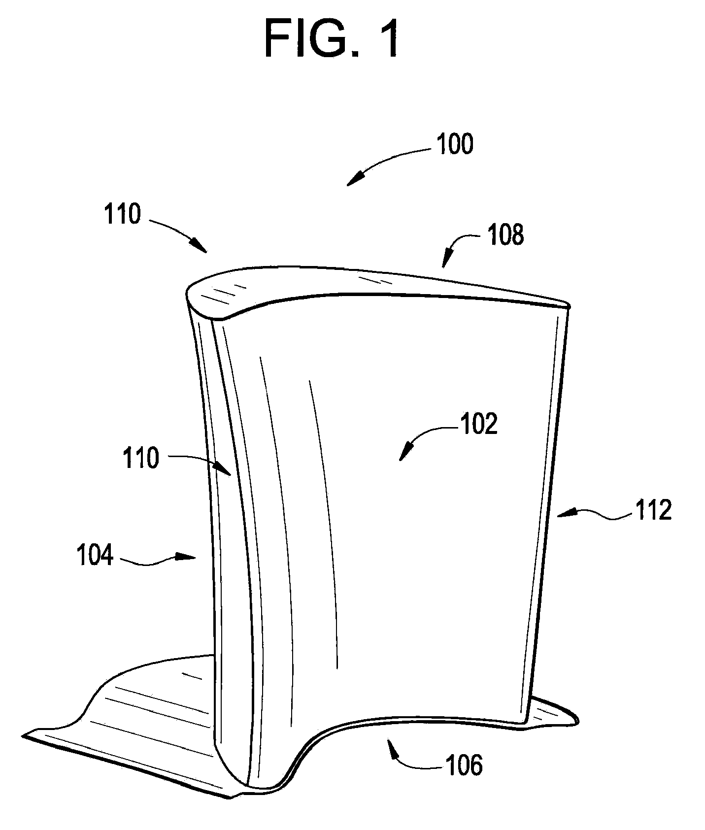
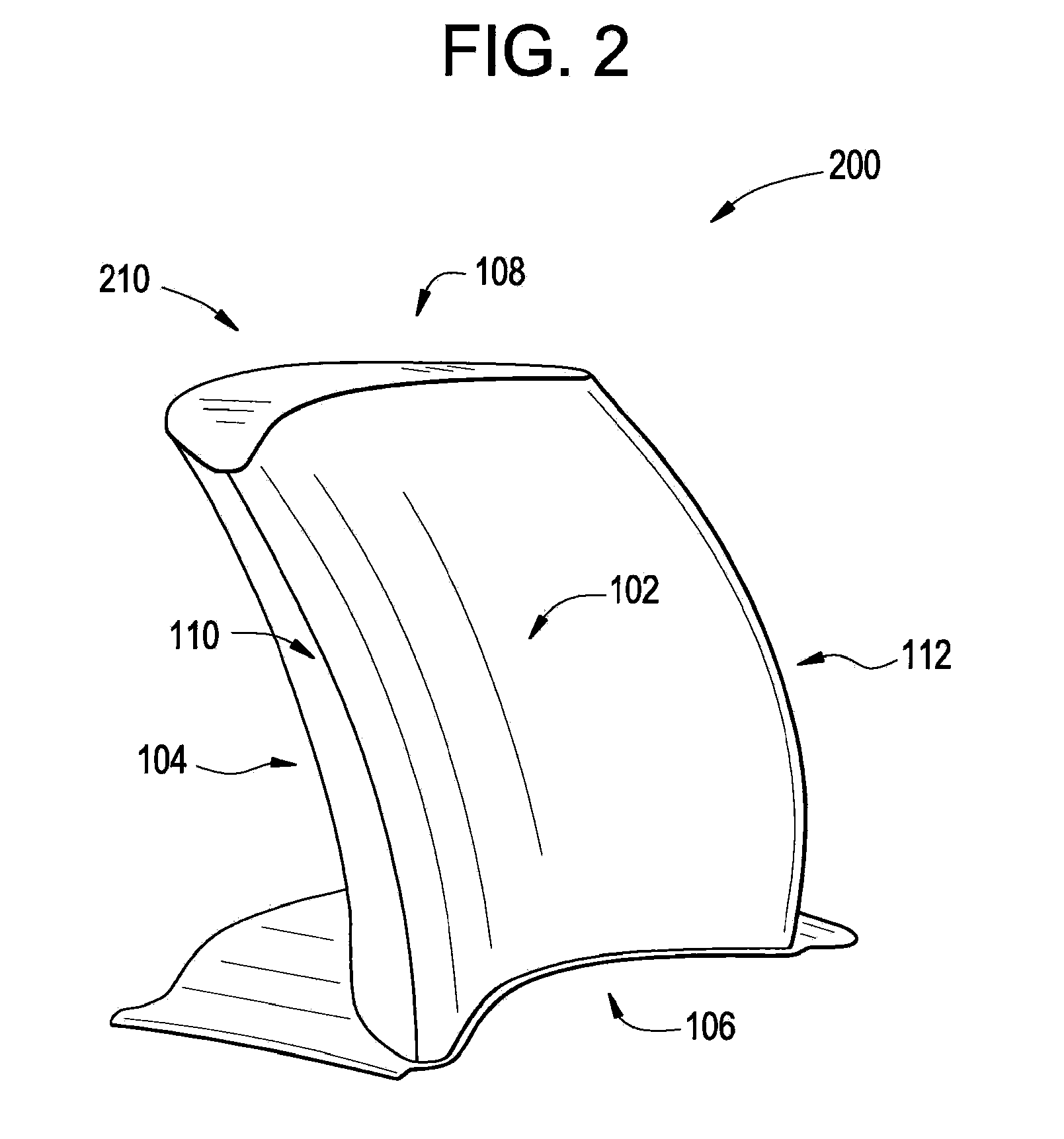
System and Method for Reducing Bucket Tip Losses
a technology of tip loss and system, applied in the field of thermomechanical turbines, can solve the problems of unsatisfactory pressure mixing and vortex flow generation, and the difficulty of tip tip loss
- Summary
- Abstract
- Description
- Claims
- Application Information
AI Technical Summary
Benefits of technology
Problems solved by technology
Method used
Image

Examples
Embodiment Construction
[0012]In the following detailed description, numerous specific details are set forth in order to provide a thorough understanding of various embodiments. However, the embodiments may be practiced without these specific details. In other instances, well known methods, procedures, and components have not been described in detail.
[0013]Further, various operations may be described as multiple discrete steps performed in a manner that is helpful for understanding embodiments of the present invention. However, the order of description should not be construed as to imply that these operations need be performed in the order they are presented, or that they are even order dependent. Moreover, repeated usage of the phrase “in an embodiment” does not necessarily refer to the same embodiment, although it may. Lastly, the terms “comprising,”“including,”“having,” and the like, as used in the present application, are intended to be synonymous unless otherwise indicated.
[0014]Exemplary embodiments ...
PUM
 Abstract
Description
Claims
Application Information