Surgical bur with Anti-chatter flute geometry

a technology of flute geometry and surgical burs, which is applied in the field of surgical burs, can solve the problems of increased spatial gap between any two flutes and in-place tissue, burs that are prone to vibration, and burs that are subject to forced vibration, and achieve the effect of reducing, if not eliminating, chatter

Inactive Publication Date: 2010-05-13
STRYKER EURO OPERATIONS HLDG LLC
View PDF11 Cites 65 Cited by
  • Summary
  • Abstract
  • Description
  • Claims
  • Application Information

AI Technical Summary

Benefits of technology

[0008]This invention is directed to the design of a new and useful surgical bur. The bur of this invention is provided with cutting edges positioned to reduce, if not eliminate, chatter that occurs during the use of the bur.

Problems solved by technology

Nevertheless, a problem associated with some burs is chatter.
Over time, the repetitive exposure of the bur flutes to these variable forces causes the bur to undergo forced vibration.
However, if the bur head is pressed against the tissue to make a deep cut, the time in which the spatial gap between any two flutes is located against the in-place tissue increases.
Consequently, there may not be enough time for tissue entrained in this gap to be discharged.
These gaps between the flutes clog.
It is believed that that build up of chips between the flutes and their cutting edges clogs the bur head.
This clogging, in turn, it is believed causes a forced vibration and the resultant chatter.

Method used


Image

  • Surgical bur with Anti-chatter flute geometry
  • Surgical bur with Anti-chatter flute geometry
  • Surgical bur with Anti-chatter flute geometry

Examples


Embodiment Construction

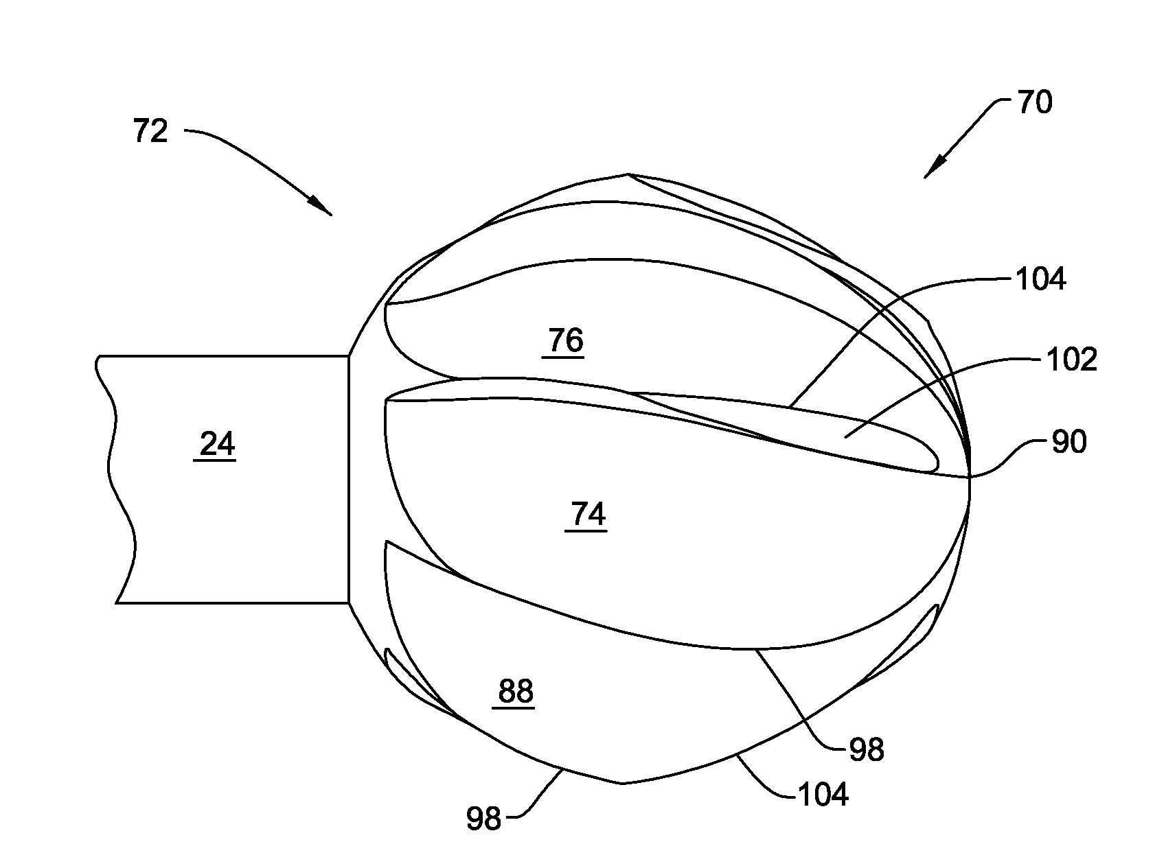
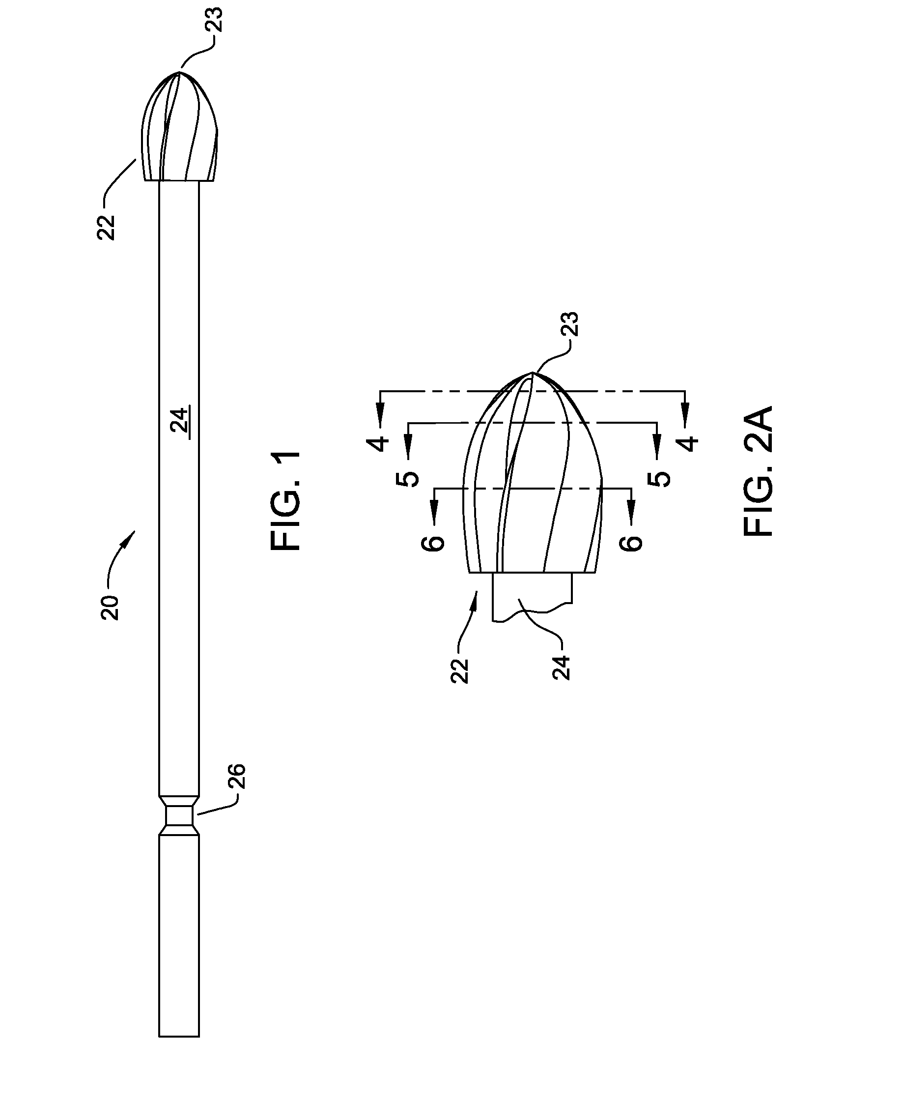
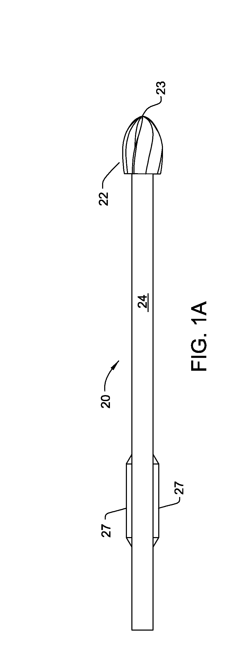
[0038]FIG. 1 illustrates a surgical bur 20 constructed in accordance with this invention. Bur 20 has a head 22 that forms the distal end of the bur. (“Distal” it shall be understood, means towards the surgical site to which the bur is applied. “Proximal” means away from the surgical site.) Bur head 22 has a distal end tip 23 that is the most forward portion of the bur 20. A shaft 24 extends proximally rearward from the bur head 22.

[0039]The proximal end of the shaft 24 is provided with coupling features 26. The coupling features 26 are geometric features that facilitate the removable engagement of the shaft 24 to a coupling assembly integral with the rotating shaft of a powered surgical tool with which bur 20 is used (tool not illustrated.) The illustrated coupling features 26 are a set of planar faces recessed relative to the outer diameter of the shaft 24. One such geometry is described and illustrated in U.S. Pat. No. 5,888,200, issued 30 Mar. 1999, Multi-Purpose Surgical Tool Sy...


PUM


Abstract

A surgical bur including a shaft with a bur head. A number of flutes are formed on the bur head. Each flute has a cutting edge. Chamfer surfaces form the front, distally directed faces of some of the burs. The flutes without chamfer surfaces having cutting edges emerge from the bur head at locations relatively close to the distal end tip of the head. The flutes over which the chamfer surfaces extend have cutting edges that start, extend proximally rearward, from locations that are, spaced proximal from the distal end tip.

Description

RELATIONSHIP TO EARLIER FILED APPLICATIONS[0001]This application is a divisional of U.S. patent application Ser. No. 11 / 943,303 filed 20 Nov. 2007 now ______. Application Ser. No. 11 / 943,303 is a continuation of PCT App. No. PCT / IB2006 / 002118, filed 17 Jul. 2006 which claims priority from U.S. Pat. App. No. 60 / 700,384 filed 19 Jul. 2005. Application Ser. No. 11 / 943,303 also claims priority from U.S. Pat. App. No. 60 / 866,735 filed 21 Nov. 2006. The contents of the priority applications are hereby explicitly incorporated herein by reference.BACKGROUND OF THE INVENTION[0002]This invention is generally related to surgical burs. More particularly, this invention is related to a surgical bur with a bur head geometry that substantially reduces chatter when the bur is applied to a surgical site.BACKGROUND OF THE INVENTION[0003]A tool used to perform a surgical procedure is the bur. A bur generally consists of a head formed from rigid material, typically metal, shaped to have a number of flu...

Claims


Application Information

Patent Timeline
Patent Type & Authority Applications(United States)
IPC IPC(8): A61B17/32
CPCA61B17/1615A61B17/32002A61B17/1673
Inventor O'SULLIVAN, DENIS F.O'DONOGHUE, DENIS
Owner STRYKER EURO OPERATIONS HLDG LLC
Why Eureka
Try Eureka