
Extendable Flange Apparatus and Methods

a technology of extendable flanges and apparatuses, applied in the field of flanges, can solve problems such as increasing the difficulty of installation

Inactive Publication Date: 2010-05-20
COFLEX SA DE CV
View PDF3 Cites 34 Cited by
  • Summary
  • Abstract
  • Description
  • Claims
  • Application Information

AI Technical Summary

Problems solved by technology

Adding a wax ring 110, however, introduces an additional source of leakage and increases the difficulty of installation.

Method used


Image

  • Extendable Flange Apparatus and Methods
  • Extendable Flange Apparatus and Methods
  • Extendable Flange Apparatus and Methods

Examples


Embodiment Construction

[0022]Various aspects of an extendable flange apparatus and related methods for installing the extendable flange between varying plumbing fixture discharges and waste drainpipe outlets according to the present disclosure are described. It is to be understood, however, that the following explanation is merely exemplary in describing the devices and methods of the present disclosure. Accordingly, several modifications, changes and substitutions are contemplated.

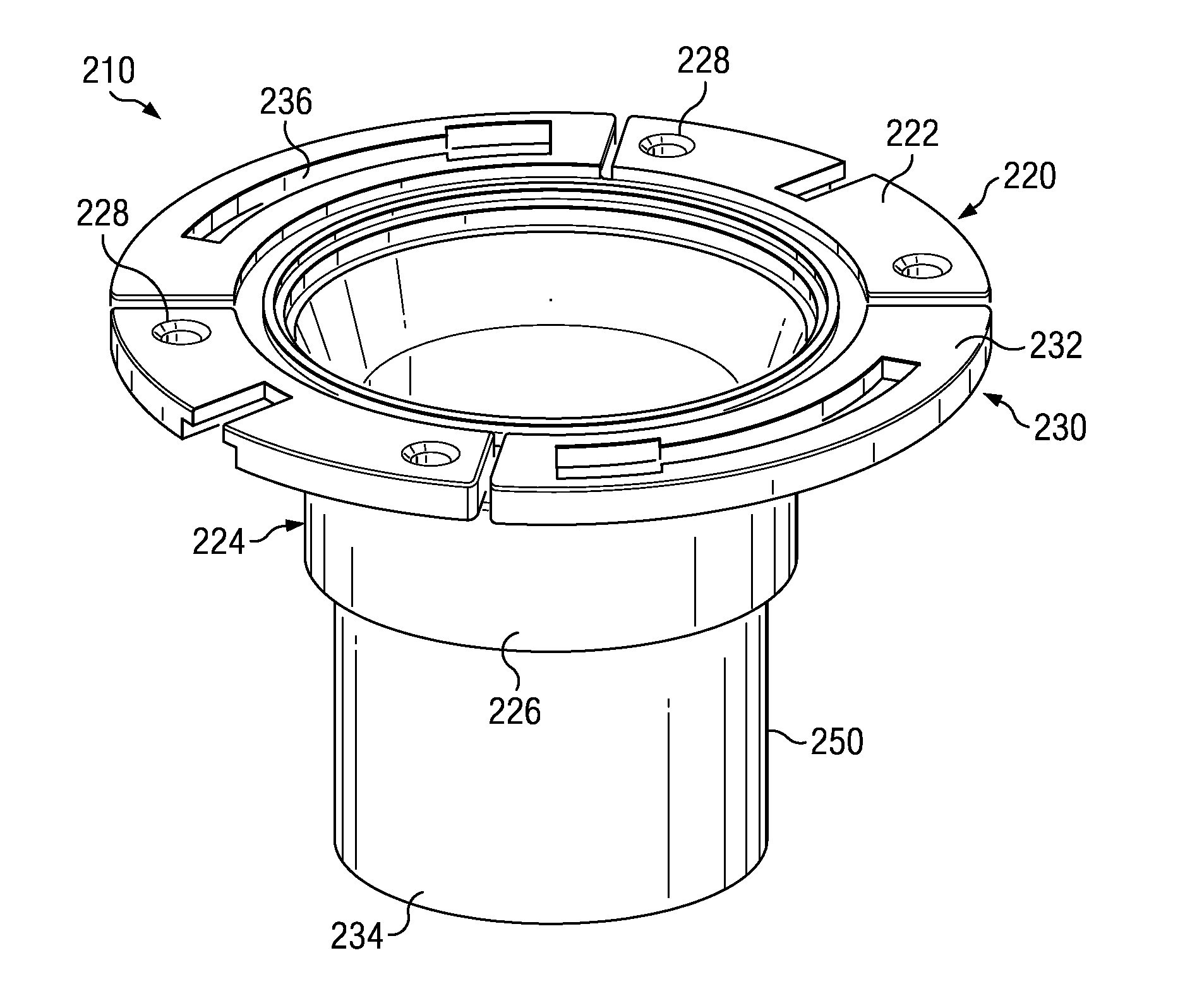
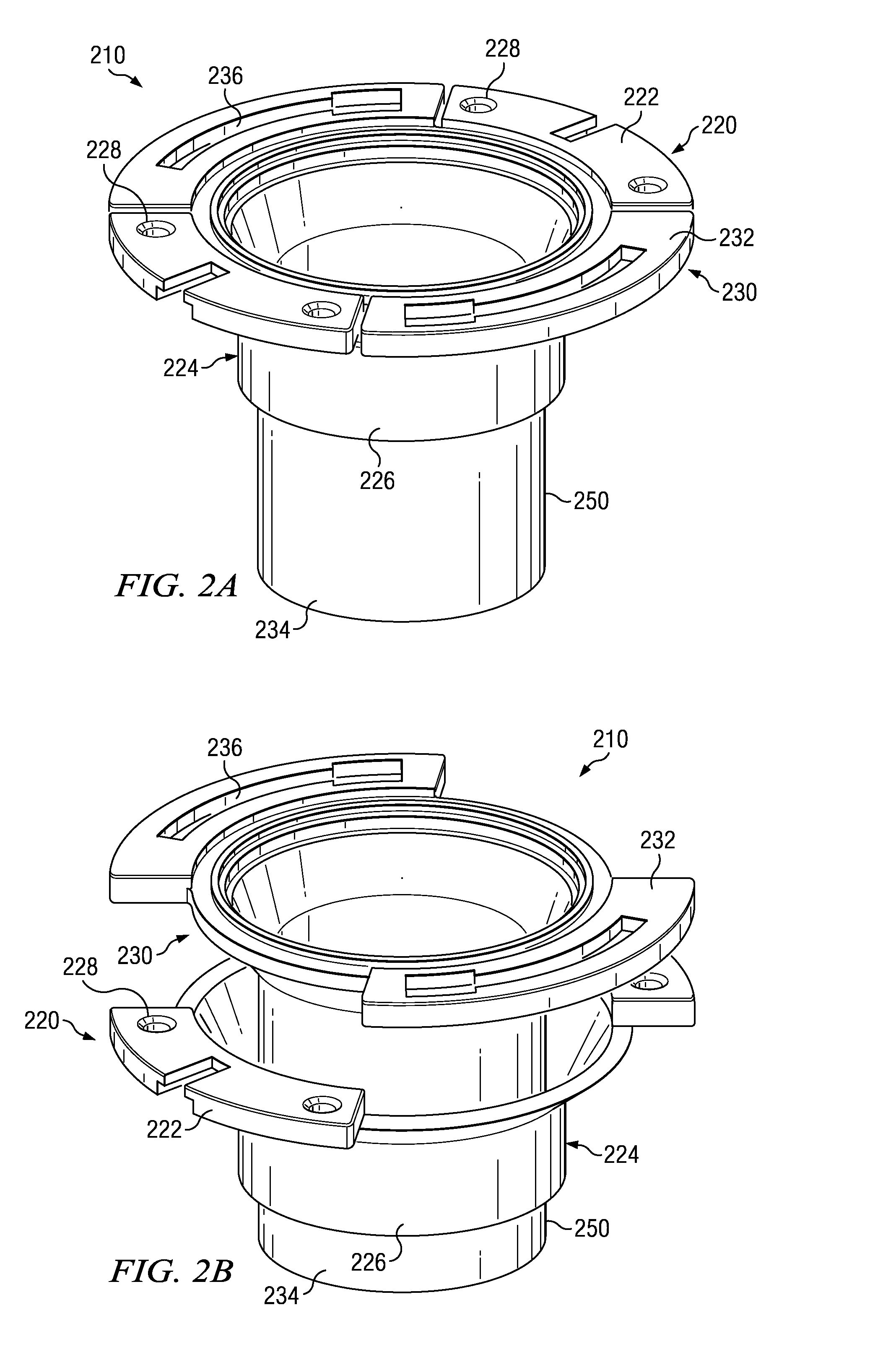
[0023]FIG. 2A is a perspective view of an extendable flange apparatus 210 in accordance with the principles of the present disclosure. The extendable flange 210 comprises an outer member 220 and an inner member 230 that are slidably coupled, thereby allowing the inner member 230 to extend upwardly from a level position to an extended position relative to the outer member 220. FIG. 2B is a perspective view of the extendable flange apparatus 210 in an extended position. As such, the extendable flange apparatus 210 is operable to ...


PUM

PropertyMeasurementUnit
Flexibilityaaaaaaaaaa

Abstract

The present disclosure generally relates to an extendable flange apparatus having an inner member slidably coupled to an outer member. The outer member includes a first flange portion and an outer tubular body with a central opening defined therethrough. The inner member includes a second flange portion and an inner tubular body operable to be at least partially disposed within the central opening of the outer tubular body of the outer member.

Description

CROSS-REFERENCE TO RELATED APPLICATION[0001]This application claims priority to U.S. Provisional. App. Ser. No. 61 / 104,221 filed on Oct. 9, 2008, which is hereby incorporated by reference in its entirety for all purposes.TECHNICAL FIELD[0002]The present disclosure generally relates to flanges for use in plumbing applications, and more particularly to flanges having extendable members.BACKGROUND[0003]Various flanges have been used to connect the discharge of a plumbing fixture to the waste drain pipe of a plumbing system. In some instances, the connection to the waste drain pipe is often found in the floor of a building, but the height of a finished floor sometimes makes the connection to the waste drain pipe inaccessible. FIG. 1 is an exploded view of the installation of a plumbing fixture 100 with a conventional, non-extendable flange apparatus 102. Due to the height of the finished floor 104, the flange apparatus 102 is seated in a recessed area below the finished floor level. As ...

Claims


Application Information

Patent Timeline
IPC IPC(8): E03D11/00B23P11/00
CPCE03D11/16Y10T29/49826F16L27/12
Inventor CORONADO, EDUARDO
Owner COFLEX SA DE CV
Features
  • Generate Ideas
  • Intellectual Property
  • Life Sciences
  • Materials
  • Tech Scout
  • Unparalleled Data Quality
  • Higher Quality Content
  • 60% Fewer Hallucinations
Learn More