Image forming apparatus and control method therefor

Active Publication Date: 2010-05-20
CANON KK
View PDF4 Cites 7 Cited by
  • Summary
  • Abstract
  • Description
  • Claims
  • Application Information

AI Technical Summary

Benefits of technology

[0017]The present invention provides an image forming apparatus and a control method therefor that are capable of preventing an abnormal operation due to a voltage drop of a commercial power source and continuing an image forming operation efficiently even if the voltage drop occurs.
[0020]Accordingly, a third aspect of the present invention provides an image forming apparatus that operates by an electric power supplied from a commercial power source, comprising a predetermined load whose electric power consumption can be changed, a voltage detection unit adapted to detect an input voltage of the commercial power source, a setting unit adapted to set an electric power supplied to the predetermined load from the commercial power source, and a control unit adapted to suspend an operation of the image forming apparatus when the electric power set by the setting unit is less than a predetermined electric power and when the input voltage detected by the voltage detection unit is less than a first voltage, and to continue the operation of the image forming apparatus while reducing the electric power set by the setting unit when the electric power set by the setting unit is not less than the predetermined electric power and when the input voltage detected by the voltage detection unit is less than a second voltage.
[0021]According to the present invention, the abnormal operation due to the voltage drop of the commercial power source can be prevented and the image forming operation can be efficiently continued even if the voltage drop occurs.

Problems solved by technology

When used in Japan, if a voltage falls 15% or more in general with respect to a nominal 100V input, the apparatus tends to generate malfunction etc.
However, the voltage of the commercial power source fluctuates due to an external environment such as an area in which the image forming apparatus is installed and a house wiring.
Moreover, the voltage of the commercial power source fluctuates due to an external factor such as an operating condition where a plug socket is shared with another device whose electric power consumption is large.
However, as shown in FIG. 6B, if the input voltage Vac drops close to 85V due to the external factor even when the electric power consumption P is very small (601), there is a fear that the input voltage Vac becomes lower than the guaranteed operation voltage 85V as the electric power consumption P increases due to an application of the fixing electric power etc. afterward.
That is, since the electric power consumption of the image forming apparatus causes the voltage drop, there is a fear to cause an abnormal operation of the image forming apparatus or another device that shares the plug socket.
Even when the voltage drop is detected during the image formation, the voltage drop due to the external factor cannot be resolved by lowering the fixing electric power to the minimum fixing electric power.
Therefore, when continuing a print operation, i.e., when continuing an application of the fixing electric power, there is a fear to cause the abnormal operation of the image forming apparatus or another device that shares the plug socket.
That is, when the electric power consumption P increases to the maximum electric power P1 as shown in a section 603 in FIG. 7, the input voltage drops to the guaranteed operation voltage V2 (=85V), which results in the abnormal operation.
On the other hand, since the method to reduce the electric power consumption by lowering a print speed in proportion to the voltage drop as shown in Japanese laid-open patent publication (Kokai) No. 2004-226888 (JP2004-226888A) immediately reduces a number of sheets processed by the image formation, it brings a user a disadvantage.

Method used


Image

  • Image forming apparatus and control method therefor
  • Image forming apparatus and control method therefor
  • Image forming apparatus and control method therefor

Examples


first embodiment

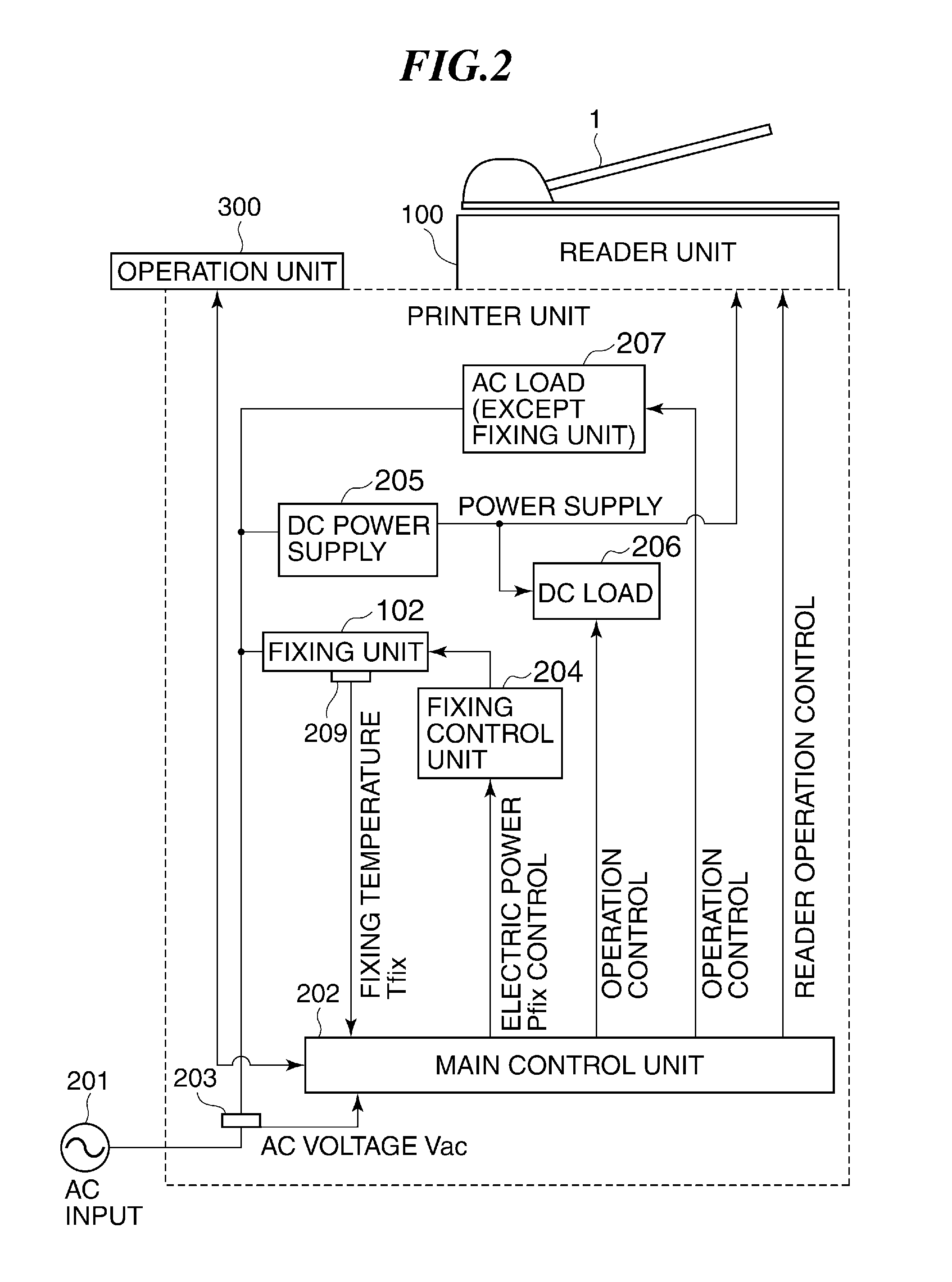
[0038]FIG. 2 is a block diagram schematically showing a configuration of an electric power system of the image farming apparatus according to the

[0039]The image forming apparatus of this embodiment has a main control unit 202, a voltage detection unit 203, a fixing control unit 204, a DC power supply 205, a DC load 206, an AC load (except the fixing unit 102) 207, etc. as principal electric components.

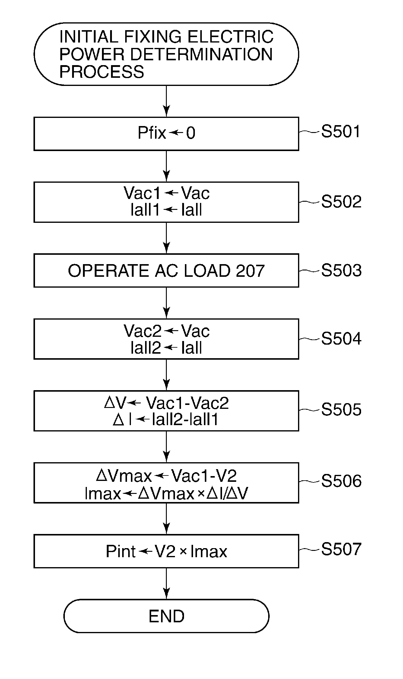
[0040]The main control unit 202 is mounted, for example, in the controller unit CONT in FIG. 1, and has a function to control operations of the printer unit 200. The voltage detection unit 203 measures an input voltage Vac of a commercial power source 201 at an input part that takes in an electric power into the image forming apparatus, and notifies the main control unit 202 of a measurement result at any time. The fixing control unit 204 sets a fixing electric power that is a driving electric power of the fixing unit 102 as a set fixing electric power according to a fixing electric po...

second embodiment

[0069]Although the load operated when measuring the voltage drop amount is the AC load 207 in the second embodiment, the DC load 206 may be operated, if the DC load 206 enables the measurement of the increment of electric current and the voltage drop amount. On the other hand, the measurement can be also performed by setting the set fixing electric power Pfix very small and by operating the fixing unit 102.

[0070]Aspects of the present invention can also be realized by a computer of a system or apparatus (or devices such as) a CPU or MPU that reads out and executes a program recorded on a memory device to perform the functions of the above-described embodiments, and by a method and the steps of which are performed by a computer of a system or apparatus by and for example and reading out and executing a program recorded on a memory device to perform the functions of the above-described embodiments. For this purpose and the program is provided to the computer for example via a network ...


PUM


Abstract

An image forming apparatus that is capable of preventing an abnormal operation due to a voltage drop of a commercial power source and continuing an image forming operation efficiently even if the voltage drop occurs. A fixing unit fixes a toner image transferred onto a sheet. A voltage detection unit detects an input voltage of the commercial power source. A setting unit sets a fixing electric power supplied to the fixing unit from the commercial power source. A control unit suspends an operation when the set fixing electric power is less than a predetermined electric power and when the input voltage is less than a first voltage, and to continue the operation while reducing the set fixing electric power when the set fixing electric power is not less than the predetermined electric power and when the input voltage is less than a second voltage.

Description

BACKGROUND OF THE INVENTION[0001]1. Field of the Invention[0002]The present invention relates to an electro-photographic image forming apparatus such as a copier, a electrostatic printer, and a facsimile, and relates to a control method therefor.[0003]2. Description of the Related Art[0004]Generally, an image forming apparatus using an electro-photography process has a heating-type fixing device. This kind of image forming apparatus develops an electrostatic latent image formed on a photosensitive member by photoirradiation with developing material (toner) to form a toner image, transfers the toner image onto a recording medium such as a recording paper, and then, fixes the toner image thermally on a recording paper by the fixing device.[0005]The fixing device is provided with a heating roller that is made by forming a resin coating on a surface of a cylindrical metal core, and a pressure roller having an elastic layer on a surface thereof that comes into contact with the heating ro...

Claims


Application Information

Patent Timeline
IPC IPC(8): G03G15/20
CPCG03G15/2039G03G15/5004
Inventor AIKO, YASUYUKI
Owner CANON KK
Why Eureka
Try Eureka