Eureka AIR delivers breakthrough ideas for toughest innovation challenges, trusted by R&D personnel around the world.

Bench press

Inactive Publication Date: 2010-05-27
HOOBLER COLIN
View PDF8 Cites 17 Cited by
  • Summary
  • Abstract
  • Description
  • Claims
  • Application Information

AI Technical Summary

Problems solved by technology

Unfortunately, most persons performing free weight exercises tend to perform the exercises in a non-optimal manner.
In addition, most people tend to move the bar up and down far too quickly which tends to work the chest considerably less and increase injury risk than if the bar was moved slower.
Unfortunately, the user simply needs to apply a vertical pressure on the bar to cause it to go up and down, although the amount of work performed by the person is limited because the user does not need to exert force to maintain the position of the bar, other than simply from sliding up and down the rails in a single plane of motor control.

Method used


Image

  • Bench press
  • Bench press

Examples


Embodiment Construction

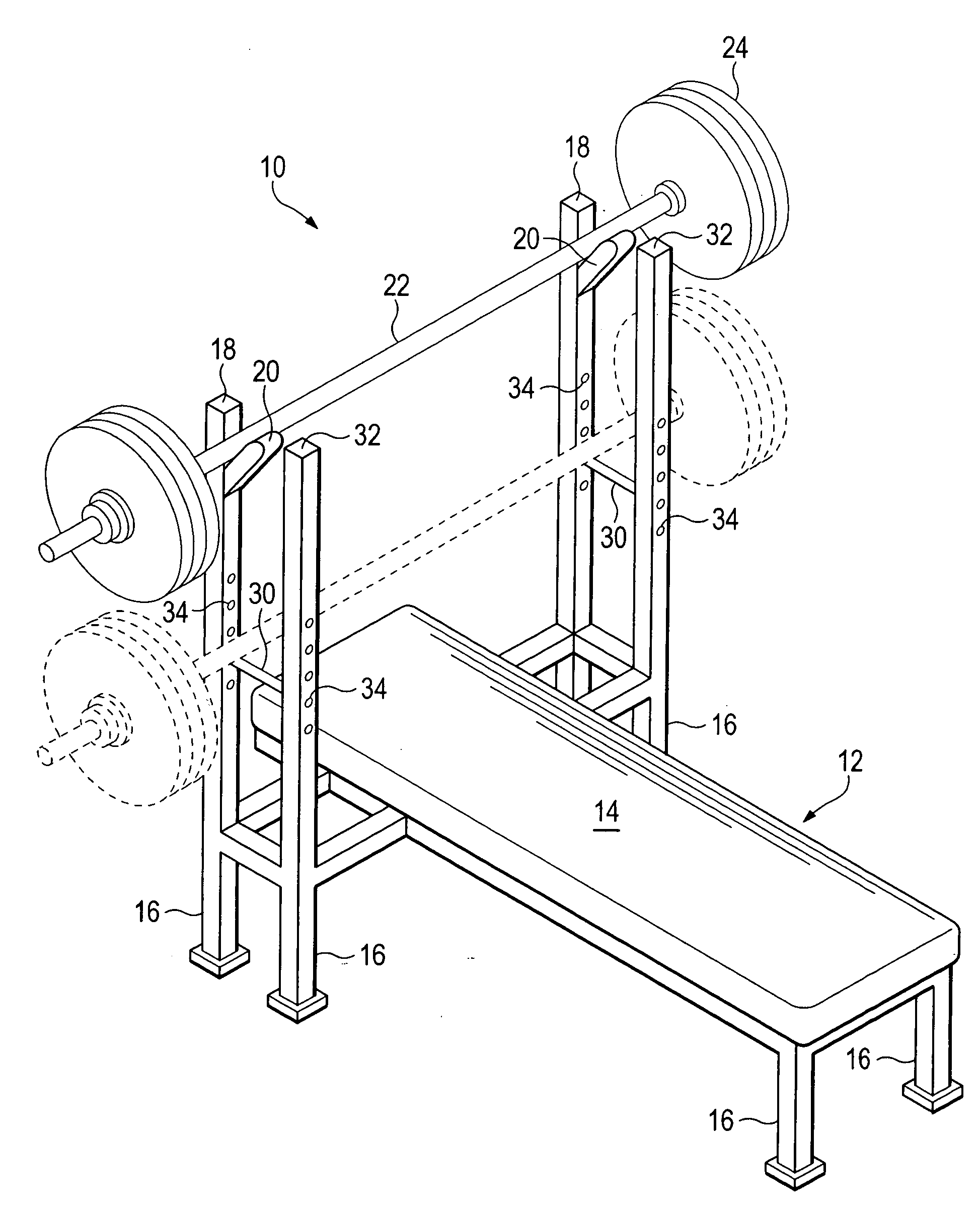
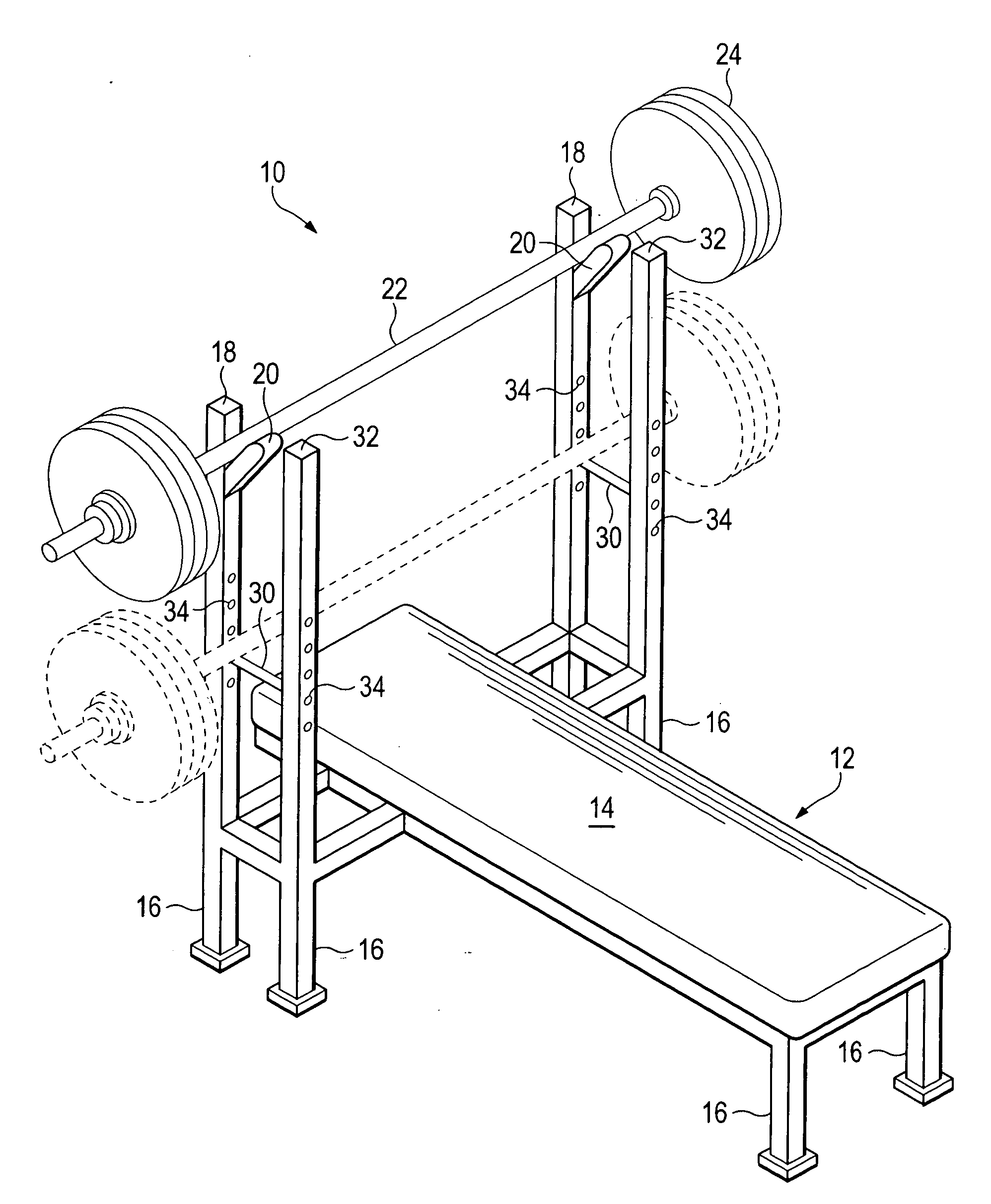
[0009]Referring to the FIGURE, a bench press apparatus 10 is preferably constructed from steel. The bench press apparatus 10 includes a horizontal bench 12, typically with a pad 14 thereon. The bench 12 is maintained off the floor by a set of legs 16. The bench includes a pair of first vertical uprights 18. Supported by each of the first vertical uprights 18 is an angled support 20. An elongate bar 22 may be supported by the angled supports 20 and extends beyond the first vertical uprights 18. A set of weights 24, typically arranged as cylindrical disks, are selectively added to the ends of the bar 22. In this manner, the person may select the desired amount of weight to lift during the exercise.

[0010]In some cases, the person may not have an available spotter to assist with lifting the weights in the event the person becomes to tired to replace the bar 22 to a height suitable for being supported by the supports 20 during the exercise. In this case, it is desirable to include a pair...


PUM


Abstract

A bench press with a first pair of upright vertical supports and a second pair of upright vertical supports.

Description

CROSS-REFERENCE TO RELATED APPLICATIONS[0001]Not applicable.BACKGROUND OF THE INVENTION[0002]The invention generally relates to exercise equipment, and more particularly, to an exercise apparatus for use during a resistance exercise, such as the bench press, squat, and curl exercises.[0003]When bench pressing, a person lies on his back which is pressed against a bench, while his feet are on the floor. With two spaced apart hands grasping a horizontal bar, optionally supporting weights proximate the ends thereof, the person raises and lowers the bar over his chest. The counterbalanced weights at the end thereof are typically changeable weights which may provide a combined weight of several hundred pounds. At the end of the exercise, the person elevates the bar one last time to place it on support members provided on a frame that extends vertically with respect to the bench.[0004]In some cases, the person is unable to raise the bar the last time to place it on the support members. In ...

Claims


Application Information

Patent Timeline
IPC IPC(8): A63B21/078
CPCA63B21/078A63B21/1457A63B2021/0786A63B21/0783A63B21/4029
Inventor HOOBLER, COLIN
Owner HOOBLER COLIN
Why Eureka
Eureka Blog
Learn More