Drillable bridge plug for high pressure and high temperature environments

a drillable, high-pressure and high-temperature technology, applied in the direction of fluid removal, sealing/packing, borehole/well accessories, etc., can solve the problems of uneven stress distribution on the segmented slip assembly and adjacent cones, limiting the axial load capacity of the slip assembly and the casing, and the inside wall of the slip assembly may not be uniformly disposed around the inside wall of the casing

Active Publication Date: 2010-06-03
SMITH INT INC
View PDF31 Cites 84 Cited by
  • Summary
  • Abstract
  • Description
  • Claims
  • Application Information

AI Technical Summary

Problems solved by technology

It has been found that once the plug is set, the slip assemblies may not be uniformly disposed around the inside wall of the casing.
This non-uniform positions of the segmented slip assemblies results in uneven stress distribution on the segmented slip assemblies and the adjacent cones.
An uneven stress distribution may limit the axial load capacities of the slip assemblies and casing, and reduce the collapse strength of the adjacent cones.
Extrusion of the sealing element causes loosening of the seal against the casing wall, and may therefore cause the downhole tool to leak.
Additionally, it has been found that downhole tools may leak at high pressures unless they include a means for increasing the seal energization, such as a pressure responsive self-energizing feature.
This may cause a loosening of the seal.
Downhole tools are also particularly prone to leak if fluid pressures on the packers are cycled from one direction to the other.
It has been found that when drilling up a bridge plug, lower components of the bridge plug may no longer engage the mandrel.
This spinning or rotation of the lower components during drilling of the plug increases the time required to drill up the plug.
Additionally, there exists a need for a bridge plug that may sustain a greater load capacity and may increase the collapse strength of components of the bridge plug.

Method used


Image

  • Drillable bridge plug for high pressure and high temperature environments
  • Drillable bridge plug for high pressure and high temperature environments
  • Drillable bridge plug for high pressure and high temperature environments

Examples


Embodiment Construction

[0048]In one aspect, embodiments disclosed herein relate generally to a downhole tool for isolating zones in a well. In certain aspects, embodiments disclosed herein relate to a downhole tool for isolating zones in a well that provides efficient sealing of the well. In another aspect, embodiments disclosed herein relate to a downhole tool for isolating zones in a well that may be more quickly drilled or milled up. In certain aspects, embodiments disclosed herein relate to bridge plugs and frac plugs.

[0049]Like elements in the various figures are denoted by like reference numerals for consistency.

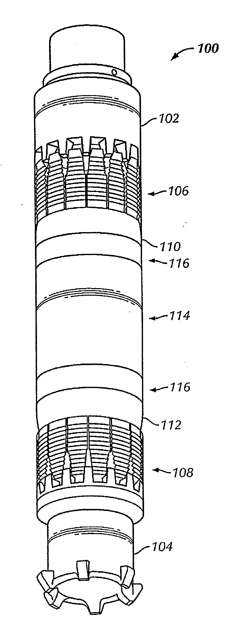
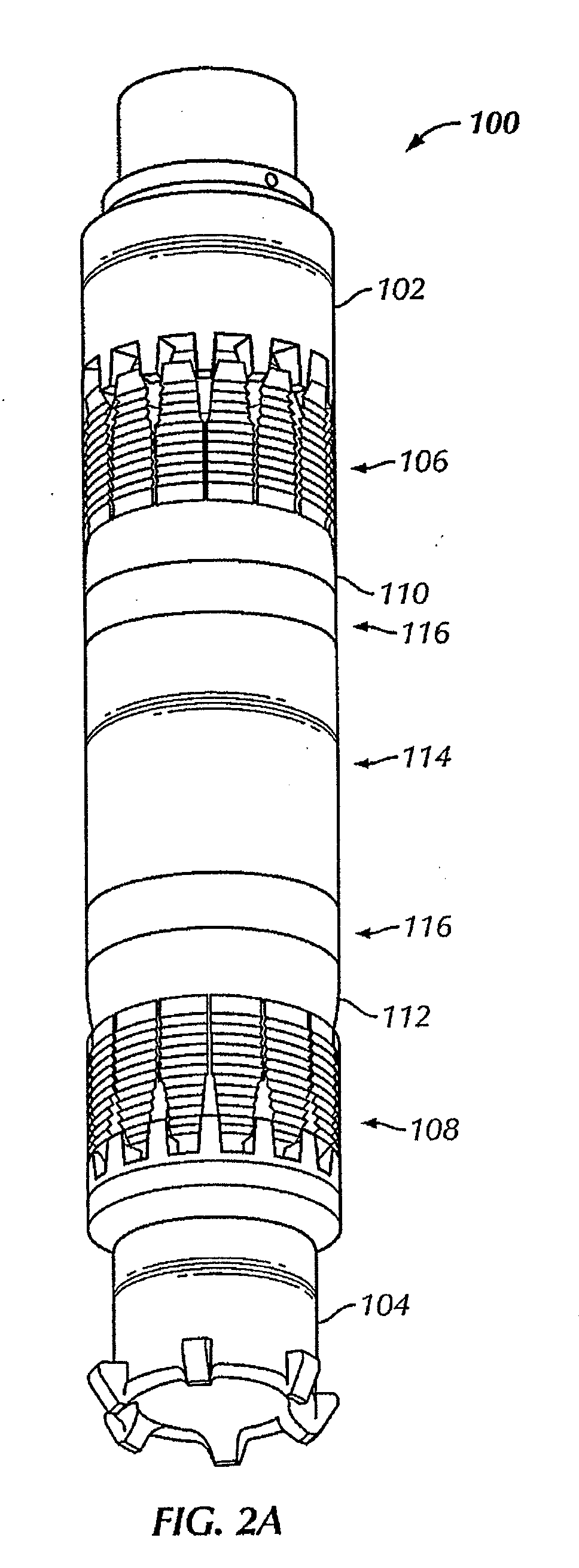
[0050]Referring now to FIGS. 2A and 2B, a bridge plug 100 in accordance with one embodiment of the present disclosure is shown in an unexpanded condition, or after having been run downhole but prior to setting it in the wellbore. The unexpanded condition is defined as the state in which the bridge plug 100 is run downhole, but before a force is applied to axially move components of the bridg...


PUM


Abstract

A drillable bridge plug includes a mandrel having external splines disposed on an outer surface of the mandrel, a sealing element disposed around the mandrel, an upper cone disposed around the mandrel proximate an upper end of the sealing element, and a lower cone disposed around the mandrel proximate the lower end of the sealing element, wherein an inner surface of the lower cone comprises internal splines configured to engage the external splines. The drillable bridge plug also includes an upper and a lower slip assembly disposed around the mandrel, and an upper and lower ring assembly each including a first segmented barrier ring, a second segmented barrier ring, and a back-up ring disposed proximate sealing element. A method of setting the drillable bridge plug and a method of removing the drillable bridge plug are disclosed.

Description

CROSS-REFERENCE TO RELATED APPLICATIONS[0001]This application claims the benefit pursuant to 35 U.S.C. §120 as a continuation-in-part application of U.S. Patent Publication No. 2008 / 0190600 filed Dec. 31, 2007, which claims benefit pursuant to 35 U.S.C. §120 as a continuation-in-part application of U.S. Pat. No. 7,424,909 filed Feb. 23, 2005. U.S. Pat. No. 7,424,909 claims priority under 35 U.S.C. §119(e) from Ser. No. 60 / 548,718, filed on Feb. 27, 2004. The above referenced applications are hereby incorporated by reference in their entirety.BACKGROUND OF INVENTION[0002]1. Field of the Invention[0003]Embodiments disclosed herein relate generally to methods and apparatus for drilling and completing well bores. More specifically, embodiments disclosed herein relate to methods and apparatus for a drillable bridge plug.[0004]2. Background Art[0005]In drilling, completing, or reworking wells, it often becomes necessary to isolate particular zones within the well. In some applications, do...

Claims


Application Information

Patent Timeline
Patent Type & Authority Applications(United States)
IPC IPC(8): E21B33/12
CPCE21B33/134
Inventor SHKURTI, PIROWOLF, JOHN C.
Owner SMITH INT INC
Why Eureka
Try Eureka