Pedestal for tracking antenna

a technology for pedestals and antennas, applied in the direction of antennas, wind-induced force reduction, antenna adaptation in movable bodies, etc., can solve the problems of antennas mounted on ships that will tend to be misdirected and other environmental stresses,

Active Publication Date: 2010-06-17
SEA TEL INC D B A COBHAM SATCOM
View PDF12 Cites 48 Cited by
  • Summary
  • Abstract
  • Description
  • Claims
  • Application Information

AI Technical Summary

Benefits of technology

[0020]Another aspect of the present invention is directed to a pedestal for a tracking antenna for obtaining rotational stabilization of the antenna about three mutually intersecting axes, said pedestal including a horizontal isolation assembly dimensioned and configured to isolate the support plate from horizontal vibration and shock of the base, a hub assembly including a support mounted on the horizontal isolation assembly rotatably supporting a rotating frame about a first azimuth axis, a vertical isolation assembly including an upright frame and a cross-level axis support slidably interconnected with a linear bearing assembly, the vertical isolation assembly may include a support spring and a dampener interconnecting the upright frame and cross-level axis support to dampen relative movement between the cross-level axis support and the upright frame, a cross-level frame pivotally mounted on the cross-level axis support about a second cross-level axis, and / or an elevation frame assembly supporting the tracking antenna and pivotally mounted on the cross-level frame about a third elevation axis.

Problems solved by technology

When a ship changes its geographical position, or when the satellite changes its position in orbit, and when the ship rolls, pitches, yaws and turns, an antenna mounted on the ship will tend to become misdirected.
In addition to these disturbances the antenna will be subjected to other environmental stresses such as vibrations caused by shipboard machinery and shocks caused by wave pounding.

Method used


Image

  • Pedestal for tracking antenna
  • Pedestal for tracking antenna
  • Pedestal for tracking antenna

Examples


Embodiment Construction

[0045]Reference will now be made in detail to various embodiments of the present invention(s), examples of which are illustrated in the accompanying drawings and described below. While the invention(s) will be described in conjunction with exemplary embodiments, it will be understood that present description is not intended to limit the invention(s) to those exemplary embodiments. On the contrary, the invention(s) is / are intended to cover not only the exemplary embodiments, but also various alternatives, modifications, equivalents and other embodiments, which may be included within the spirit and scope of the invention as defined by the appended claims.

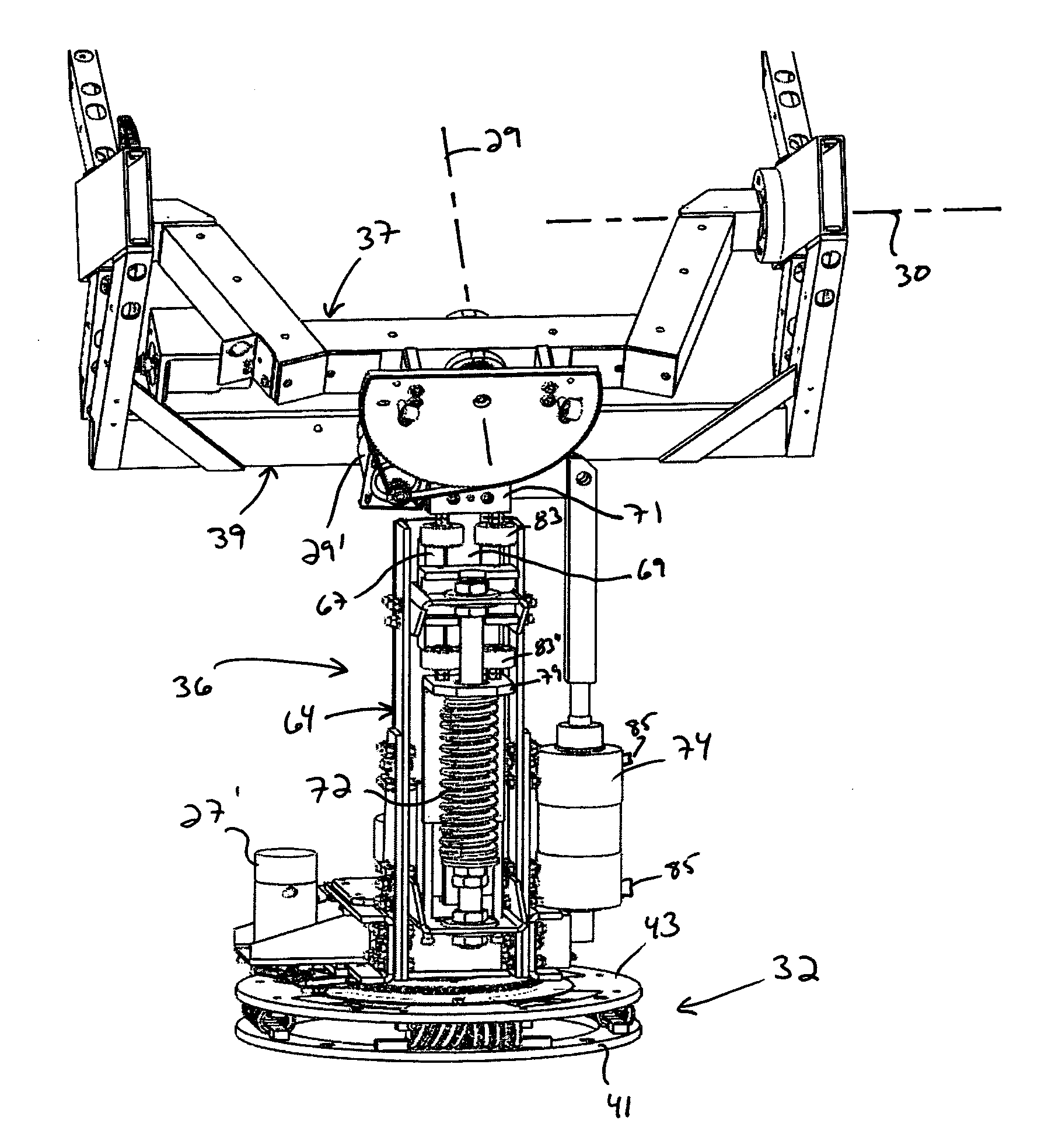
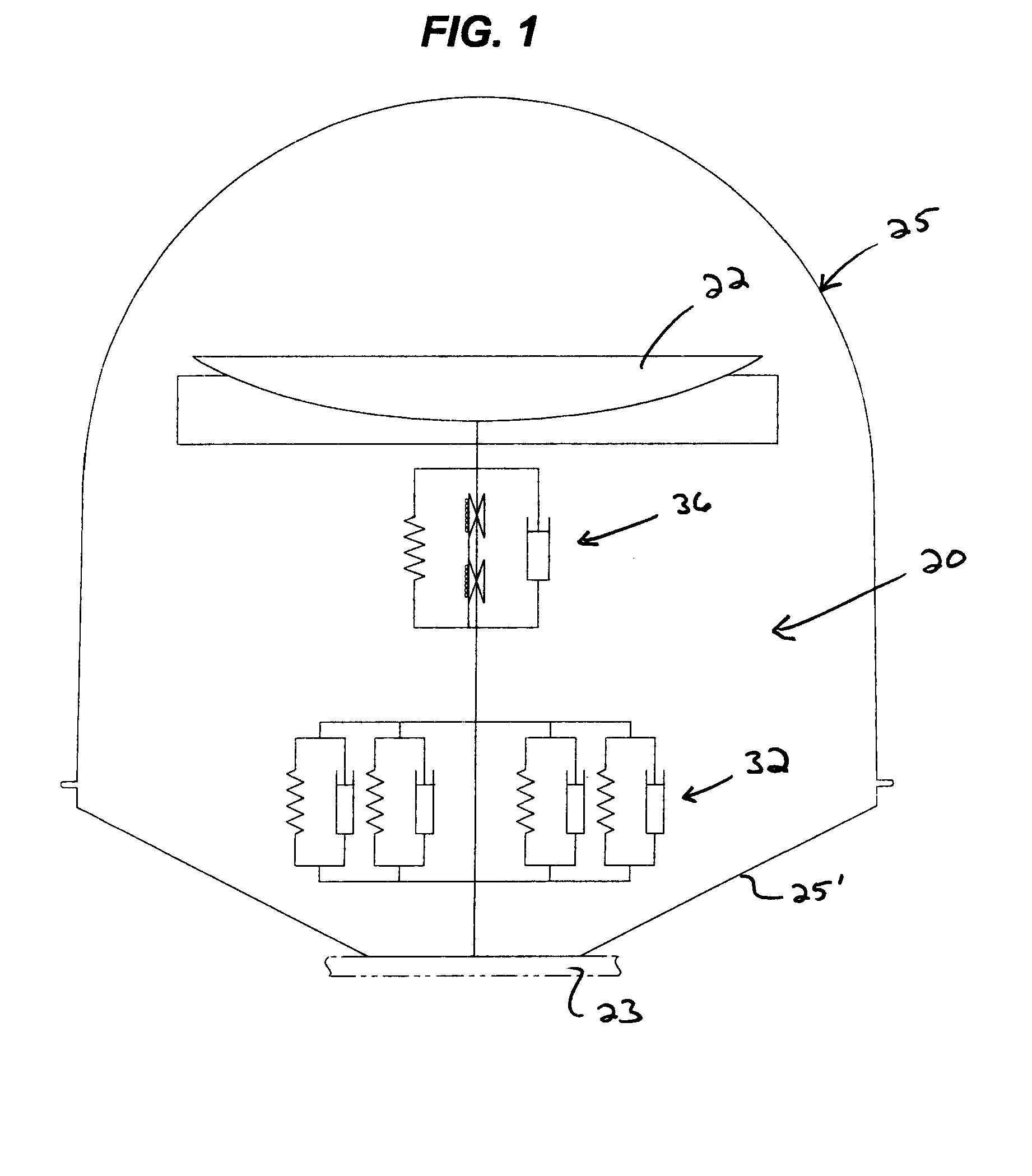
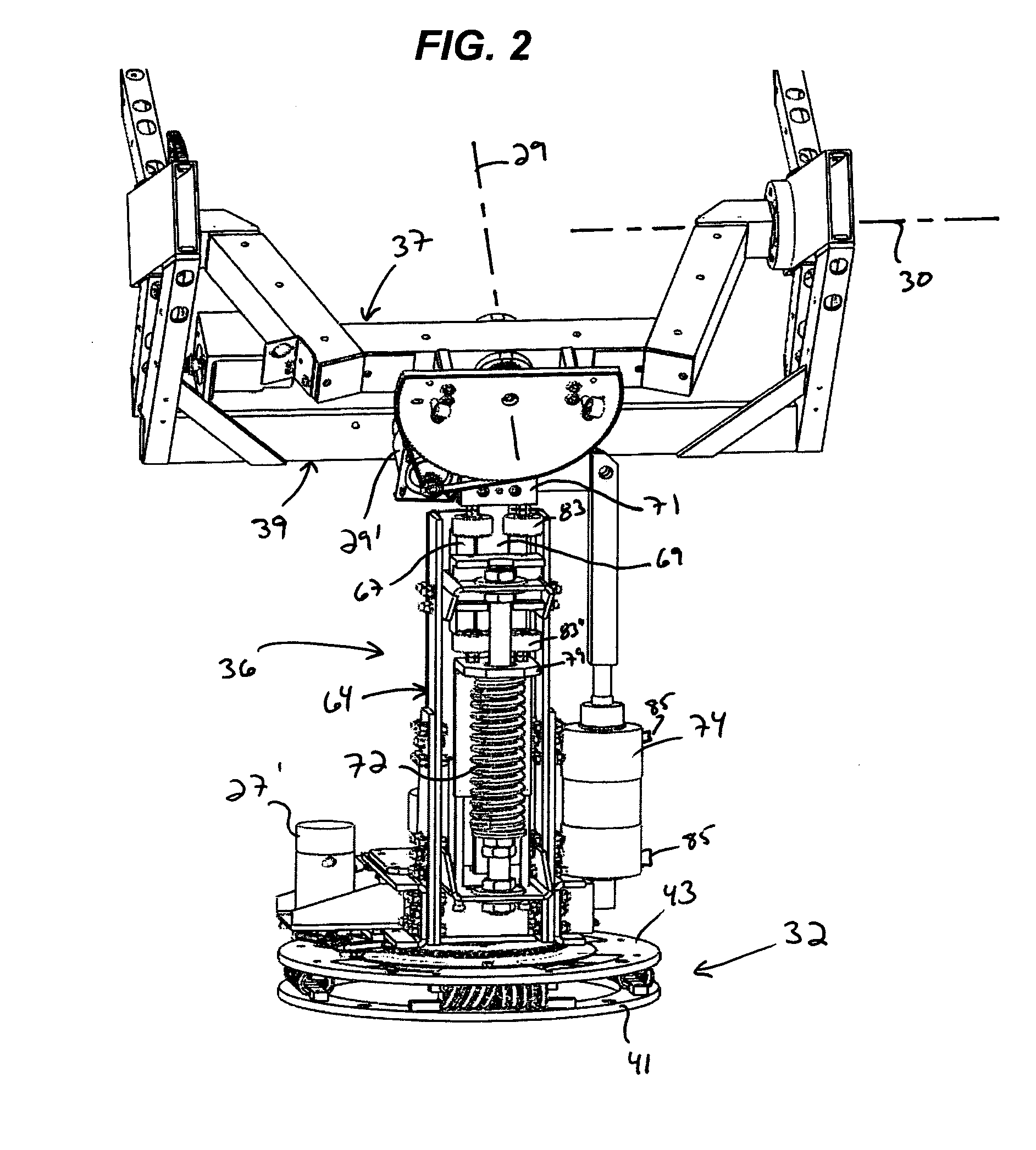
[0046]In its simplest form the present invention includes supporting structural members, bearings, and drive means for positioning various rotating and pivoting structural members which are configured to align a tracking antenna about three axis, an azimuth axis, a cross-level axis, and an elevation axis. Antenna stabilization is achi...


PUM


Abstract

A pedestal for tracking antenna includes a horizontal isolation assembly dimensioned and configured to isolate the support plate from horizontal vibration and shock of the base ring, a hub assembly including a support mounted on the horizontal isolation assembly rotatably supporting a rotating frame about a first azimuth axis, a vertical isolation assembly including an upright frame and a cross-level axis support slidably interconnected with a linear bearing assembly, the linear bearing assembly having a profiled rail slidably received within a complementary shaped bearing block, wherein the profiled rail can not twist axially relative to the bearing block, a cross-level frame pivotally mounted on the cross-level axis support about a second cross-level axis, and/or an elevation frame assembly supporting the tracking antenna and pivotally mounted on the cross-level frame about a third elevation axis.

Description

CROSS-REFERENCES TO RELATED APPLICATIONS[0001]This application claims priority to U.S. Provisional Patent Application No. 61 / 122,698 filed Dec. 15, 2008, entitled PEDESTAL FOR TRACKING ANTENNA, the entire contents of which is incorporated herein for all purposes by this referenceBACKGROUND OF THE INVENTION[0002]1. Field of the Invention[0003]This invention relates, in general, to pedestals for tracking antenna and more particularly to satellite tracking antenna pedestals used on ships and other mobile applications and methods for their use.[0004]2. Description of Related Art[0005]The invention is especially suitable for use aboard ship wherein an antenna is operated to track a transmitting station, such as a communications satellite, notwithstanding roll, pitch, yaw, and turn motions of a ship at sea.[0006]Antennas used in shipboard satellite communication terminals typically are highly directive. For such antennas to operate effectively they must be pointed continuously and accurat...

Claims


Application Information

Patent Timeline
Patent Type & Authority Applications(United States)
IPC IPC(8): H01Q3/00
CPCH01Q1/005H01Q1/12H01Q1/18H01Q3/08H01Q1/34
Inventor PATEL, TRUSHAR D.
Owner SEA TEL INC D B A COBHAM SATCOM
Why Eureka
Try Eureka