Femoral Implant For Hip Arthroplasty

a technology of femoral implants and hip arthroplasty, which is applied in the field of implants, can solve the problems of rare practice results and the inability of most conventional hip prostheses to permit extreme maneuvers, and achieve the effect of improving range of motion and reducing thickness

Inactive Publication Date: 2010-06-17
INST OF ORTHOPEDIC RES & EDUCATION
View PDF3 Cites 13 Cited by
  • Summary
  • Abstract
  • Description
  • Claims
  • Application Information

AI Technical Summary

Problems solved by technology

Although it is intended that a total hip replacement will fully restore the normal range of motion and ease of movement of the hip joint, this goal is rarely achieved in practice.
However, most conventional hip prostheses do not permit extreme maneuvers with compound rotations of the hip that are becoming more common and desirable as hip replacement patients become progressively younger and increasingly more active.

Method used


Image

  • Femoral Implant For Hip Arthroplasty
  • Femoral Implant For Hip Arthroplasty
  • Femoral Implant For Hip Arthroplasty

Examples


example 1

Range of Motion Comparison

[0064]The range of motion of embodiments of femoral necks designed in accordance with the principles described herein were also compared to a conventional 12 mm conical neck of similar strength. As shown in FIG. 10, the increase in range of motion of maneuvers highly susceptible to dislocation such as sit to stand and shoe-tying was about 5° and about 3°, respectively.

[0065]FIG. 10 also illustrates an apparent decrease in external rotation / extension maneuvers to prosthetic impingement during pivoting and rolling maneuvers of embodiments described herein compared to the conventional 12 mm neck. This difference is generally irrelevant, however, as both necks easily surpassed the limits of each maneuver as estimated by the experimental data. For example, normal patients considerably younger (and likely more flexible) than the typical total hip patient (49.7±5.0 yrs. vs. 65-70 yrs.) have limits of external rotation during rolling and pivoting still below those ...

example 2

Strength Analysis of Femoral Implant Design

[0066]Computer modeling and testing of a femoral neck constructed in accordance with the principles described herein was performed to ensure sufficient strength to pass the stringent ASTM standard F1612-95 described previously. A 3D computer model of the neck was placed on a standard stem model. The maximum stresses in the neck were calculated using finite element analyses, and were compared virtually with a conventional 12 mm conical neck known to have sufficient strength. Each model was meshed in 3D using tetrahedral elements (average size=1.0 mm). Each model was then positioned in 10° of adduction and 9° of flexion and constrained below the stem's osteotomy as required in ISO Standard 7206-6. A 5340N load was applied inferiorly to the center of the head using the worst case scenario for head offset (head position along the neck axis). As shown in FIG. 11, the maximum principal stresses and the maximum von Mises stresses were compared for...


PUM


Abstract

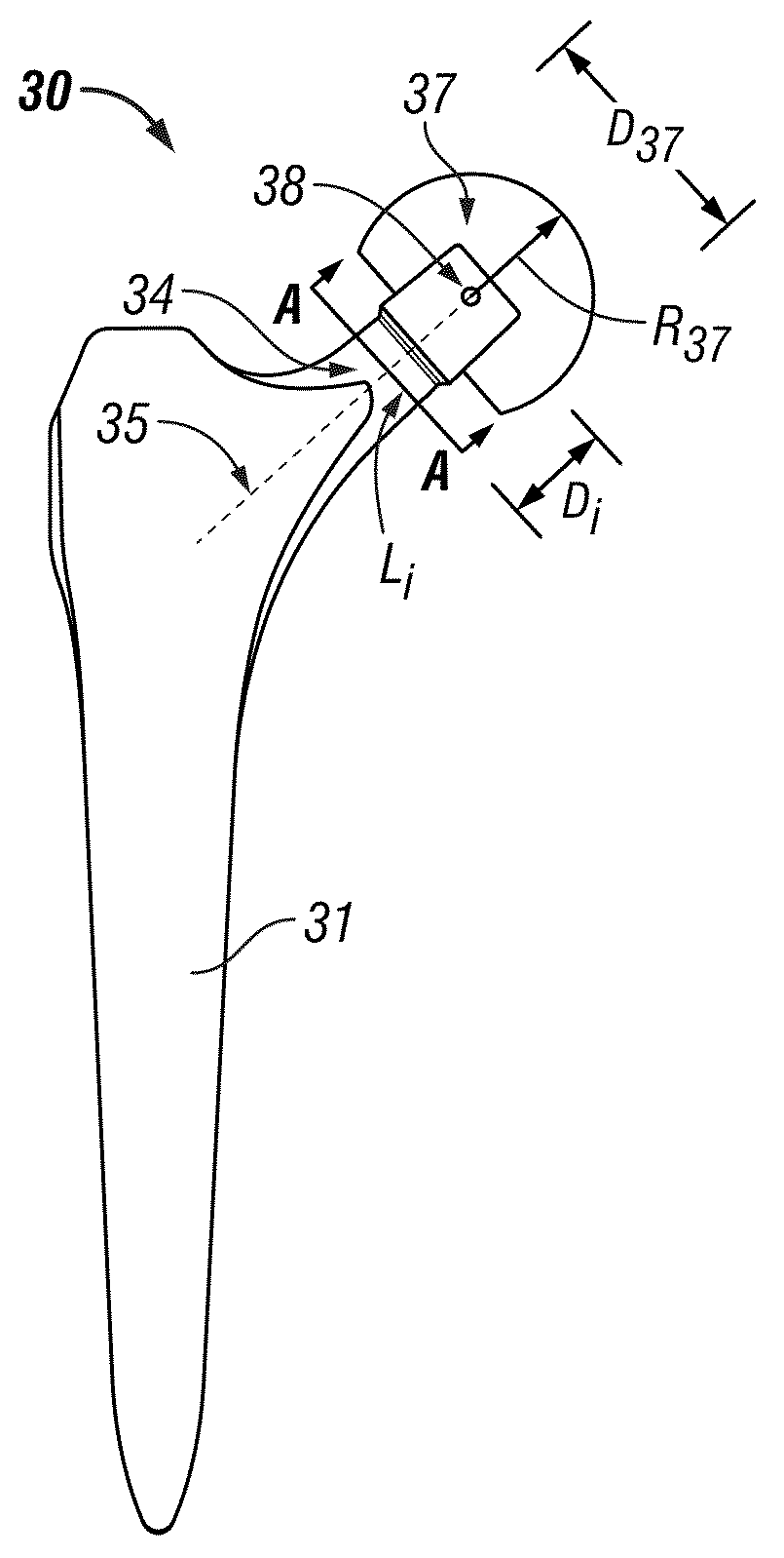
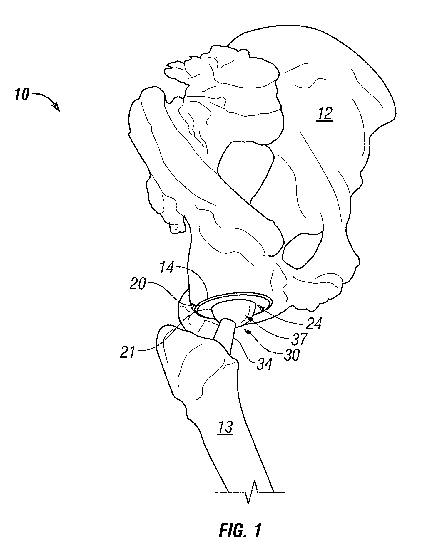
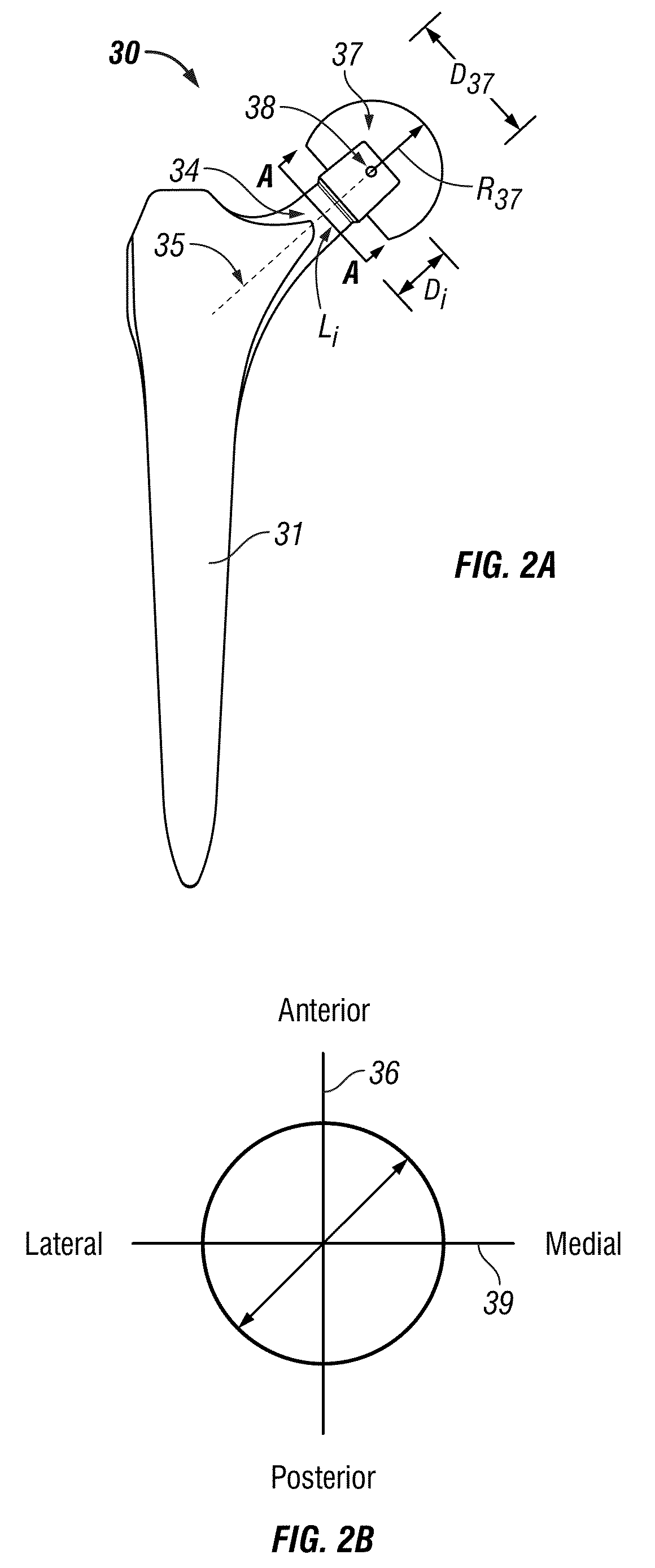
A prosthetic femoral implant for use in hip arthroplasty comprises an elongate femoral stem. In addition, the femoral implant comprises a femoral neck having a central axis, a first end integral with the femoral stem, and a second end distal the femoral stem. A transverse cross-section of the femoral neck includes a medial-lateral axis and an anterior-posterior axis. Moreover, a reference circle bisected by the medial-lateral axis and passing through the medial-most point and the lateral-most point has a diameter equal to a maximum medial-lateral width Wml of the transverse cross-section and an area A1. The lateral-most anterior segment of the transverse cross-section includes a laterally expanded area extending outside the reference circle, the laterally expanded area having an area A2 that is at least 7% of one-fourth of the area A1 of the reference circle.

Description

CROSS-REFERENCE TO RELATED APPLICATIONS[0001]This application claims benefit of U.S. provisional application Ser. No. 61 / 109,227 filed Oct. 29, 2008, and entitled “Femoral Implant with Improved Range of Joint Motion,” which is hereby incorporated herein by reference in its entirety for all purposes.STATEMENT REGARDING FEDERALLY SPONSORED RESEARCH OR DEVELOPMENT[0002]Not applicable.BACKGROUND[0003]1. Field of the Invention[0004]The invention relates generally to implants. More particularly, the invention relates to a femoral implant to enhance the range of motion of the hip joint following a total hip arthroplasty.[0005]2. Background of the Invention[0006]Although it is intended that a total hip replacement will fully restore the normal range of motion and ease of movement of the hip joint, this goal is rarely achieved in practice. Many artificial hip prostheses allow the patient sufficient motion to perform basic activities such as walking and sitting. However, most conventional hip...

Claims


Application Information

Patent Timeline
Patent Type & Authority Applications(United States)
IPC IPC(8): A61F2/32
CPCA61F2/3609A61F2230/0004A61F2002/30112
Inventor THOMPSON, MATTHEW T.PATEL, RIKIN V.
Owner INST OF ORTHOPEDIC RES & EDUCATION
Why Eureka
Try Eureka