Hip prostheses

a technology for prostheses and hips, applied in the field of hip prostheses, can solve the problems of dislocation problems, polyethylene wear, and exacerbated dislocation problems, and achieve the effects of reducing polyethylene wear, reducing or preventing dislocation of the femoral stem head, and increasing or at least not compromising the ability of the shell/liner

Active Publication Date: 2006-09-28
SMITH & NEPHEW INC
View PDF103 Cites 20 Cited by
  • Summary
  • Abstract
  • Description
  • Claims
  • Application Information

AI Technical Summary

Benefits of technology

[0008] Various embodiments of the present invention include various structures and techniques for reducing polyethylene wear while at the same time increasing or at least not compromising ability of the shell / liner (or simply a shell) in a hip prosthesis to reduce or prevent dislocation of the femoral stem head.

Problems solved by technology

Even though bipolar prostheses are well beyond the first generation of design and implementation, a number of issues remain.
These include (1) the potential for dislocation of the femoral stem head relative to the shell / liner; and (2) polyethylene wear issues.
The dislocation problem is exacerbated because dislocations often require surgical intervention to reestablish the prosthetic / hip joint.
However, overemphasis on dislocation prevention can reduce range of motion between the femoral stem and the shell / liner.
Additionally, previous designs are limited by the extent to which the polyethylene can “stretch” to accommodate the stem head in a capture fit.
That extent may be insufficient for optimal dislocation prevention in non-locking ring designs.
Split rings, however, present their own sets of issues, including potential to expand and contract in diameter even after installed which can in turn introduce polyethylene wear issues in addition to unacceptable “pistoning” of the stem head in the liner with potential polyethylene wear and stability complications.
Polyethylene wear has been recognized as an undesirable effect sometimes caused by articulating and non-articulating relative motion between a polyethylene surface and another surface such as, for instance, a metal surface such as that of a bearing in a hip prosthesis.
One reason that polyethylene wear is considered serious is that even a very small volume of polyethylene debris actually includes a great number of polyethylene particles.
These particles are believed to cause osteolysis when they escape into nearby bone and tissue.

Method used


Image

  • Hip prostheses
  • Hip prostheses
  • Hip prostheses

Examples


Embodiment Construction

a. Particular Bipolar Prosthetic Structures for Improving Material Wear and Dislocation Properties.

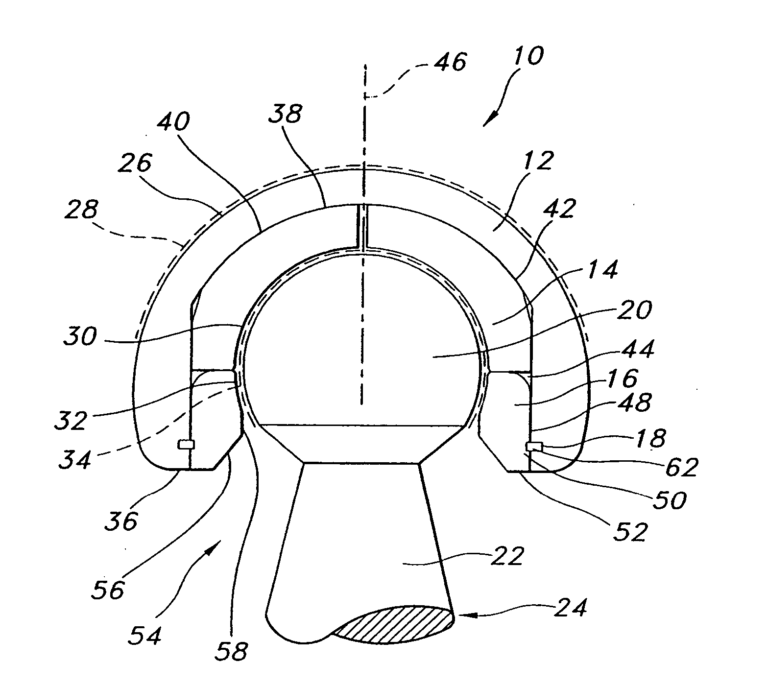
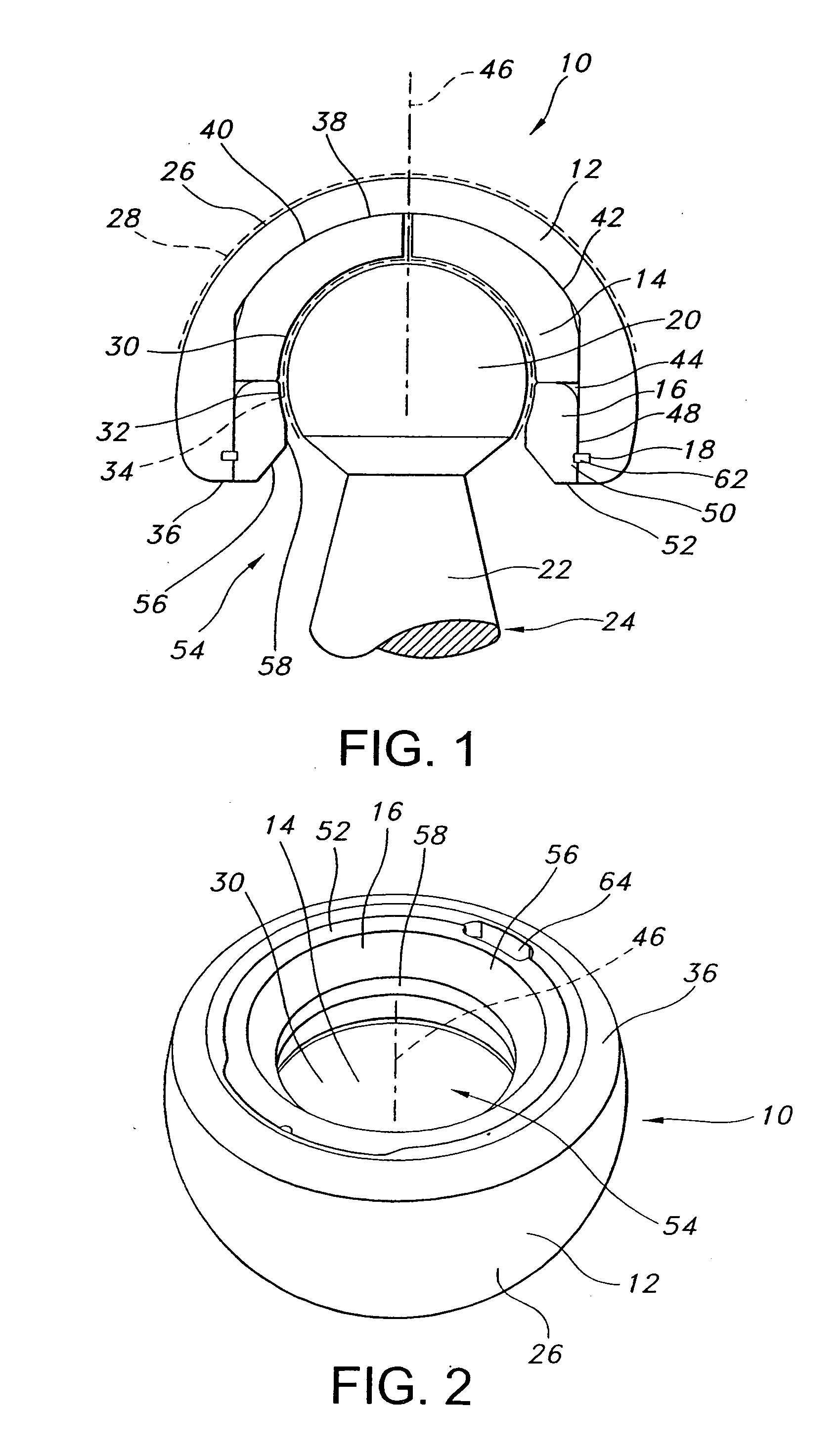
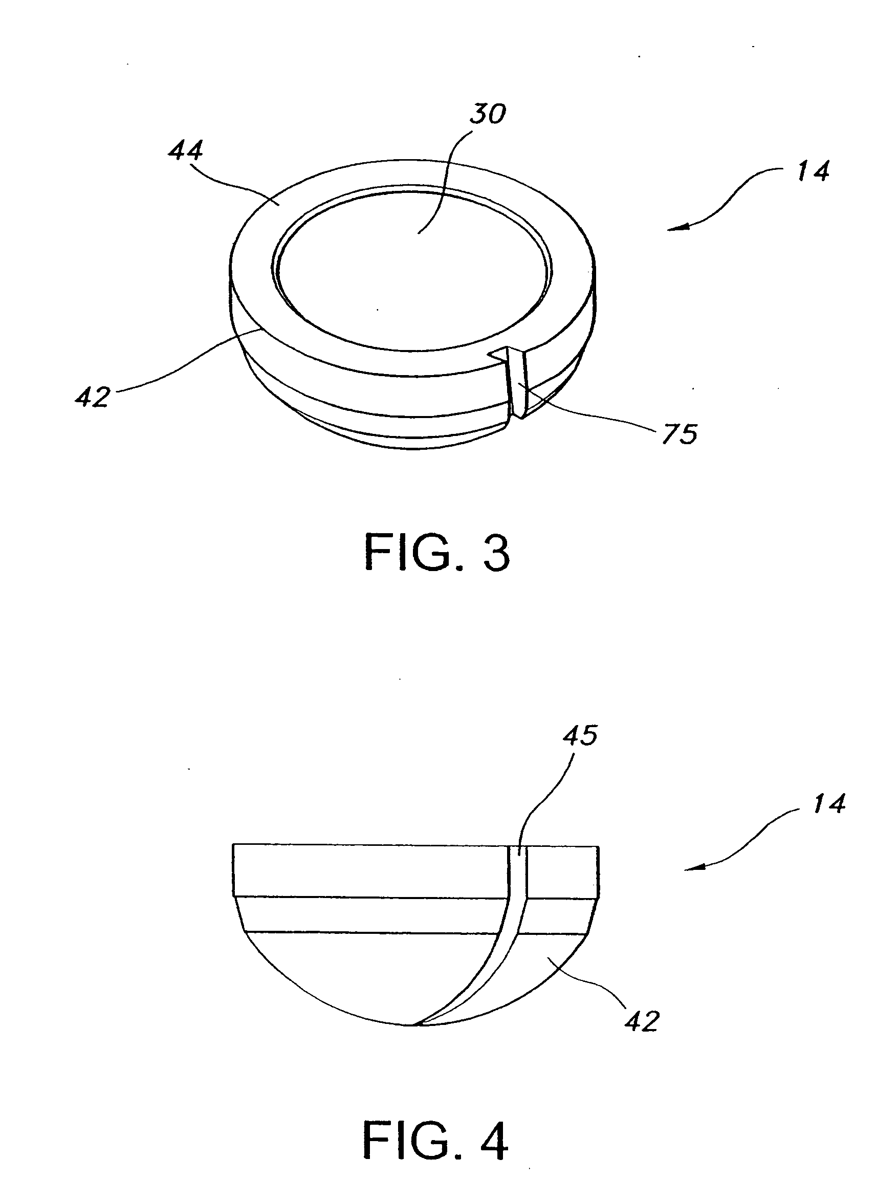
[0035]FIG. 1 is a cross-sectional view showing a preferred embodiment of a bipolar prosthesis 10 according to certain aspects of the present invention. Prosthesis 10 generally includes a shell 12 which receives a liner 14 and a locking ring 16 which may be held in place by a retainer 18. The prosthesis 10 is adapted to fit within and articulate, or fit in an articulating relationship with, the acetabulum. “Articulating relationship” means a physical relationship that allows relative motion or movement between two components of a prosthesis in a manner that corresponds to motion or movement of two body parts relative to each other, such as bone structure on opposing sides of a joint such as an ankle, knee, hip, wrist, elbow or shoulder. For instance, prosthesis 10 and a femoral stem it accommodates are connected in an articulating relationship, while the liner fixed within the prosthe...


PUM

PropertyMeasurementUnit
wear resistanceaaaaaaaaaa
diameteraaaaaaaaaa
strength propertiesaaaaaaaaaa

Abstract

Bipolar prostheses which include various structures and other techniques for optimizing material wear and mechanical strength properties. Such prostheses feature, for example, improved resistance to polyethylene wear while also reducing potential for dislocation of the femoral stem from the prosthesis. Such techniques and structures include varying wear resistance and mechanical strength treatment in various components of the prostheses or portions of those components as desired to improve, accentuate or optimize wear performance and dislocation reduction, locking ring structural features, structures for retaining locking rings in the bipolar prosthesis shell, and structures for limiting or reducing movement or rotation of locking rings and liners in bipolar prosthesis shells.

Description

[0001] This application is a continuation-in-part of U.S. patent application Ser. No. 10 / 243,502, the entire contents of which are hereby incorporated by reference. This invention relates to improved prostheses, including bipolar prostheses, suited to reduce polyethylene wear and potential of femoral / acetabular dislocation.BACKGROUND [0002] Bipolar prostheses generally provide two bearing surfaces between the (artificial) femoral head and the acetabulum. The first bearing surface is the typically smooth outer surface of the bipolar prosthesis shell, which may be formed of metal, ceramic material or as otherwise desired. A liner, conventionally formed of polyethylene material such as ultra high molecular weight polyethylene, may be adapted to fit tightly within the shell and provide an inner bearing surface which receives and cooperates with the femoral head in an articulating relationship to track and accommodate the relative movement between the femur and the acetabulum. [0003] Thi...

Claims


Application Information

Patent Timeline
Patent Type & Authority Applications(United States)
IPC IPC(8): A61F2/32A61F2/34A61F2/00A61F2/30A61F2/36A61F2/46
CPCA61F2/30767A61F2/32A61F2/34A61F2/36A61F2/3609A61F2/3662A61F2002/30332A61F2002/30354A61F2002/30367A61F2002/30378A61F2002/30403A61F2002/30495A61F2002/30497A61F2002/30604A61F2002/30822A61F2002/30934A61F2002/3208A61F2002/3233A61F2002/3241A61F2002/3493A61F2002/3611A61F2002/3625A61F2002/3631A61F2002/365A61F2002/4641A61F2220/0025A61F2220/0033A61F2310/00011A61F2310/00179A61F2310/00634A61F2002/3283A61F2002/3291
Inventor LAMBERT, RICHARDMCLEAN, TERRYKELMAN, DAVID
Owner SMITH & NEPHEW INC
Why Eureka
Try Eureka