Method and system of mapping femoral head for acetabular prosthesis alignment

a technology of acetabular prosthesis and femoral head, which is applied in the field of system and method of implanting a hip prosthesis, can solve the problems of inability to verify the correct placement of the acetabular shell component intraoperatively, adversely affecting postoperative performance, function, range of motion, and joint stability

Active Publication Date: 2011-04-21
SMITH & NEPHEW INC
View PDF8 Cites 24 Cited by
  • Summary
  • Abstract
  • Description
  • Claims
  • Application Information

AI Technical Summary

Problems solved by technology

Due to the nature of hip arthroplasty, it is sometimes difficult to verify correct placement of an installed acetabular shell component intraoperatively.
If an acetabular shell is misaligned prior to impacting, cementing, screwing, or otherwise affixing it to a prepared acetabulum, any subsequent trialing procedures and / or final implantation of the prosthesis may be compromised.
Misalignment of an acetabular shell component may reduce articulation surface area, thereby adversely affecting postoperative performance, function, wear rate, range of motion, and joint stability.
These methods, while effective, require additional resources, personnel, additional instruments, and / or expensive machinery.
However, precise orientation angles of the acetabular shell component cannot be readily determined from fluoroscopic imaging.
These methods, while effective, do not provide a finely calibrated visual feel-good device to a surgeon.
However, most indicia are generally found in the lip area or at the bottom of a tapered recess within the femoral heads and not located on an articulating surface.
However, it is believed that such indicia are not configured to determine a spatial orientation of an acetabular shell component.

Method used


Image

  • Method and system of mapping femoral head for acetabular prosthesis alignment
  • Method and system of mapping femoral head for acetabular prosthesis alignment
  • Method and system of mapping femoral head for acetabular prosthesis alignment

Examples


Embodiment Construction

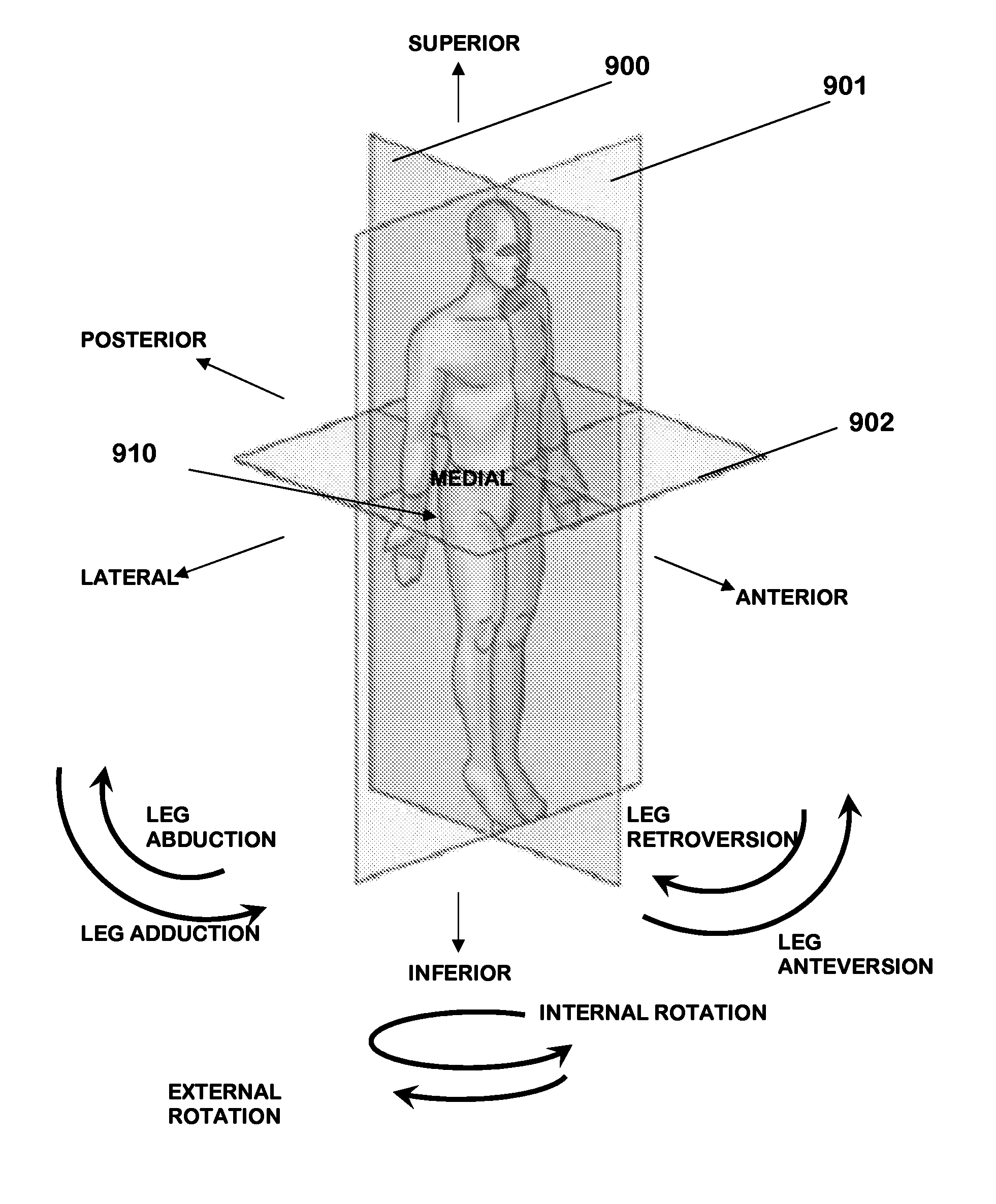
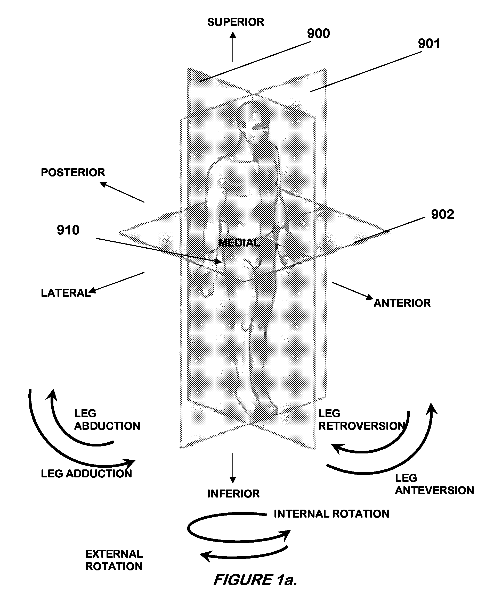
[0062]The Figures generally relate to geographically mapping a trial femoral head in order to assess the orientation of an acetabular shell component during trial reduction.

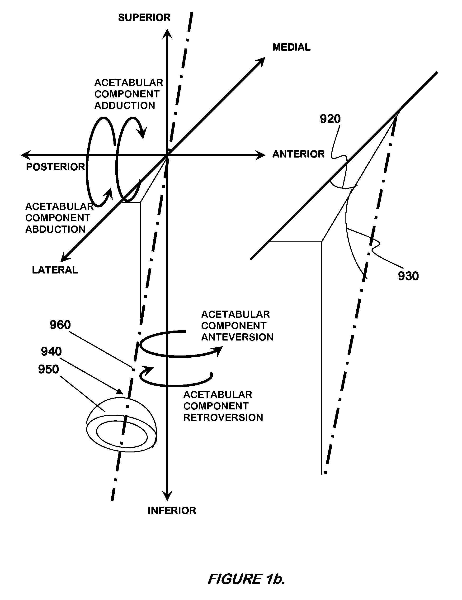
[0063]FIGS. 1a and 1b illustrate a right hip joint (910) and various directions of anatomical movement related to the human leg. FIG. 1a shows a hip joint (910), which allows a human leg to move anteriorly within a sagittal plane (900) during anteversion or posteriorly within the sagittal plane (900) in retroversion. Hip joint (910) also allows a human leg to move laterally within a coronal plane (910) during abduction and medially within the coronal plane (910) during adduction. Internal-external rotation may be enabled by twisting the leg about the superior inferior axis and within a transverse plane (902) while the leg is in full extension. However, rotation may be performed during any state of flexion, version, and / or abduction. FIG. 1b generally depicts a proper orientation of a natural acetabulum and correc...


PUM

PropertyMeasurementUnit
insertion angleaaaaaaaaaa
anteversion angleaaaaaaaaaa

Abstract

An apparatus for orienting a prosthetic femoral head relative to an acetabulum comprises a femoral stem and a femoral head member. The femoral stem is configured to be received within the intramedullary canal of a femur. The femoral head member is configured to couple to the femoral stem and further configured to be received in the acetabulum. The femoral head member further comprises an indicia configured to orient a relative position of the prosthetic femoral head to the acetabulum such that the indicia signifies proper relative position of the prosthetic femoral head in the acetabulum.

Description

CROSS-REFERENCE TO RELATED APPLICATIONS[0001]This application claims the benefit of U.S. Provisional Application No. 61 / 031,230, filed Feb. 25, 2008. The disclosure of the application is incorporated by reference in its entirety.BACKGROUND[0002]1. Field[0003]The present invention relates generally to systems and methods of implanting a hip prosthesis and more particularly to a system and method of determining prosthesis orientation using indicia.[0004]2. Related Art[0005]Trialing during prosthesis implantation is generally essential in joint arthroplasty. Trialing steps ensure proper placement and function as well as assess range of motion and stability. In some cases, for example, in hip arthroplasty, an acetabular shell component needs to be implanted before trialing can begin. Likewise, other instances such as in knee arthroplasty, a tibial tray component needs to be implanted before trialing can begin.[0006]In total hip arthroplasty, an acetabulum is normally prepared by reaming...

Claims


Application Information

Patent Timeline
Patent Type & Authority Applications(United States)
IPC IPC(8): A61F2/32
CPCA61B19/5202Y10S623/914A61B2019/446A61B2019/5204A61B2019/5206A61B2019/521A61B2019/5437A61B2019/5441A61B2019/5445A61F2/34A61F2/3609A61F2/4684A61F2002/30617A61F2002/365A61F2002/4696A61F2250/0097A61B19/54A61B2090/3945A61B90/30A61B2090/309A61B90/94A61B2090/304A61B2090/306A61B90/39A61B2090/3937A61B2090/3941C07D455/06C07B2200/07
Inventor MCMAHON, STEPHEN NMIALLEN, CHARLES WAYNEKELMAN, DAVID C.
Owner SMITH & NEPHEW INC
Why Eureka
Try Eureka