Cannulated femoral hip implant apparatus

a technology of femoral hip and implant device, which is applied in the field of implants, can solve the problems of reducing freedom of people, increasing pain during daily activities, and difficult and painful day functions

Inactive Publication Date: 2005-10-27
CHAPPUIS JAMES L
View PDF4 Cites 22 Cited by
  • Summary
  • Abstract
  • Description
  • Claims
  • Application Information

AI Technical Summary

Problems solved by technology

Although the ability to walk, run, and freely move about is often taken for granted, an injured hip can greatly reduce a person's freedom.
An injured hip can make these every day functions difficult and painful to perform.
A breakdown of any component of the hip results in increased pain during daily activities, such as walking or running.
Osteoarthritis results in dissipation of the cartilage and synovial fluid due to wear and tear over time.
Other causes are rheumatoid arthritis and inflammation of the joint, which increase...

Method used


Image

  • Cannulated femoral hip implant apparatus
  • Cannulated femoral hip implant apparatus

Examples


Embodiment Construction

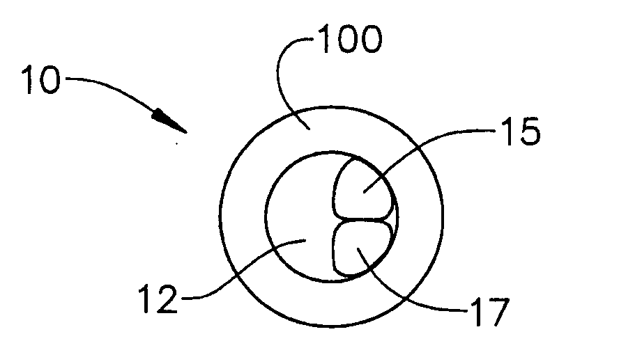
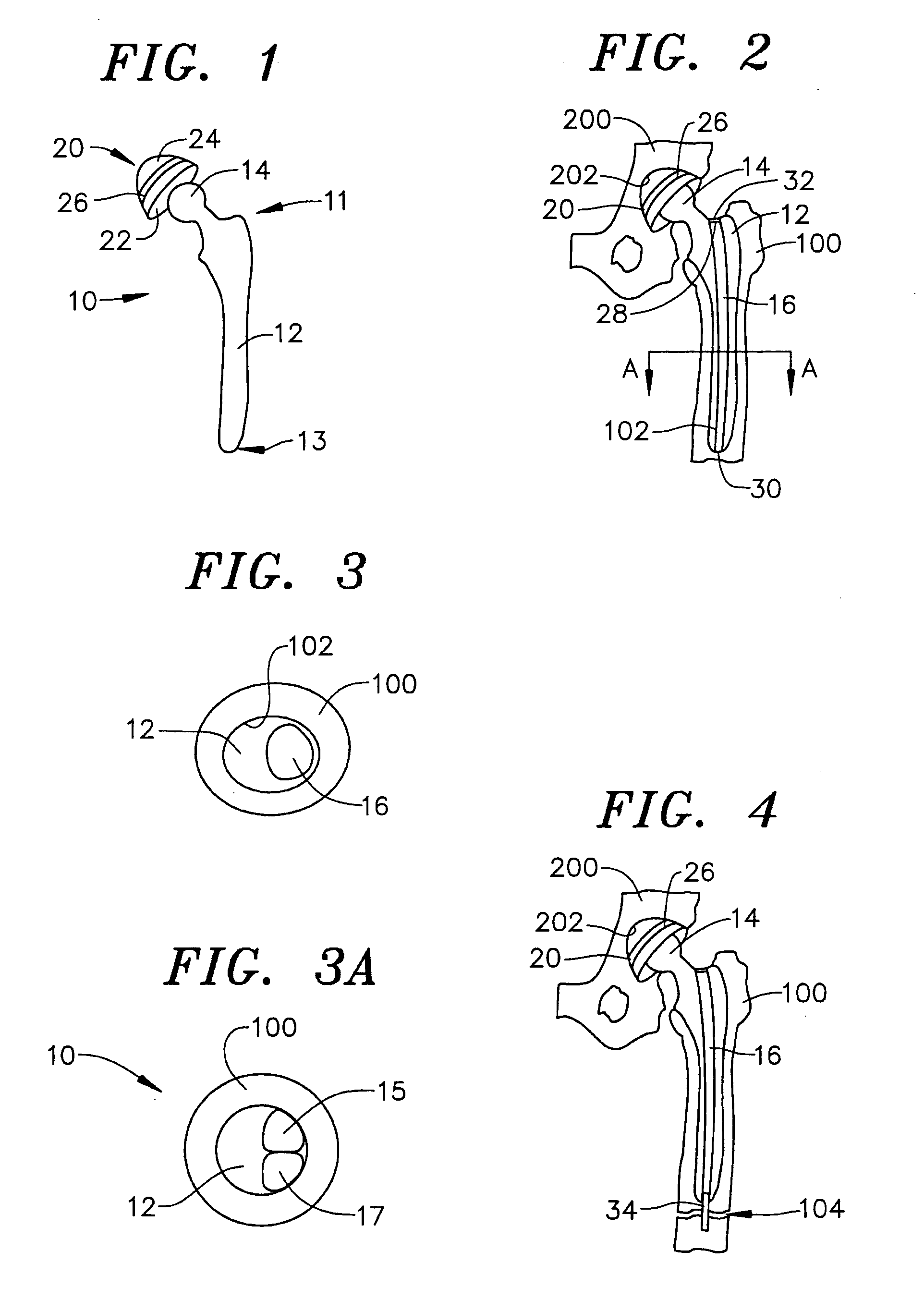
[0019]FIGS. 1 and 2 illustrate one preferred embodiment of a cannulated femoral hip implant 10. The cannulated femoral hip implant 10 comprises a femoral stem 12 and a femoral ball 14. The femoral stem 12 extends from the femoral ball 14 and is defined by a proximal end 11 and a distal end 13. In one configuration the femoral stem 12 tapers down in diameter toward the distal end 13 from the proximal end 11 such that a diameter of the femoral stem 12 toward the proximal end 11 is greater than a diameter of the femoral stem 12 toward the distal end 13. It should be understood, however, that any suitable sizing and proportioning configuration can be implemented. The femoral ball 14 has a substantially spherical shape.

[0020] As shown in FIG. 1, the cannulated femoral hip implant 10 further comprises a femoral cup 20. The femoral cup 20 is defined by an inner surface 22 and an outer surface 24. The inner surface 22 of the femoral cup 20 is concave such that the inner surface 22 substant...


PUM


Abstract

The femoral hip implant is defined by a femoral ball and a femoral stem. The femoral stem has a proximal end, a distal end and a length. The femoral stem extends from the femoral ball and terminates at the distal end. The femoral stem is arranged and configured to be received by a femur bone. A method of use is also provided.

Description

CROSS-REFERENCE TO RELATED APPLICATION [0001] This application claims priority to copending U.S. provisional application entitled, “Cannulated Femoral Hip Implant Apparatus,” having Ser. No. 60 / 561,610, filed on Apr. 13, 2004, which is entirely incorporated herein by reference.FIELD OF THE INVENTION [0002] The present invention is generally related to implants used in the medical field and more particularly, is related to a cannulated femoral hip implant apparatus. BACKGROUND OF THE INVENTION [0003] Although the ability to walk, run, and freely move about is often taken for granted, an injured hip can greatly reduce a person's freedom. An injured hip can make these every day functions difficult and painful to perform. [0004] The hip is a ball and socket joint formed at the joining of the femur and the pelvis. The femur, also known as the thighbone, terminates at a ball formed at the upper tip. The socket of the joint is formed in the pelvis. Joint function is facilitated by the ball...

Claims


Application Information

Patent Timeline
IPC IPC(8): A61B17/68A61F2/28A61F2/30A61F2/32A61F2/34A61F2/36
CPCA61B17/68A61F2230/0008A61F2/32A61F2/34A61F2/36A61F2/3662A61F2/367A61F2/3676A61F2002/2817A61F2002/30113A61F2002/30125A61F2002/30785A61F2002/30878A61F2002/3422A61F2002/3611A61F2002/3664A61F2002/3694A61F2230/0006A61F2/30744A61F2002/342
Inventor CHAPPUIS, JAMES L.
Owner CHAPPUIS JAMES L
Why Eureka
Try Eureka