
Optical reader quality factor

a technology of optical readers and quality factors, applied in the field of manufacturing, field service, maintenance and performance aspects of optical readers and components, can solve the problems of loss of calibration of readers, change in characteristics, cost, unfriendly customers, etc., and achieve the effect of little or no down time for users

Active Publication Date: 2010-06-24
IGT GLOBAL SOLUTIONS CORP
View PDF4 Cites 0 Cited by
  • Summary
  • Abstract
  • Description
  • Claims
  • Application Information

AI Technical Summary

Benefits of technology

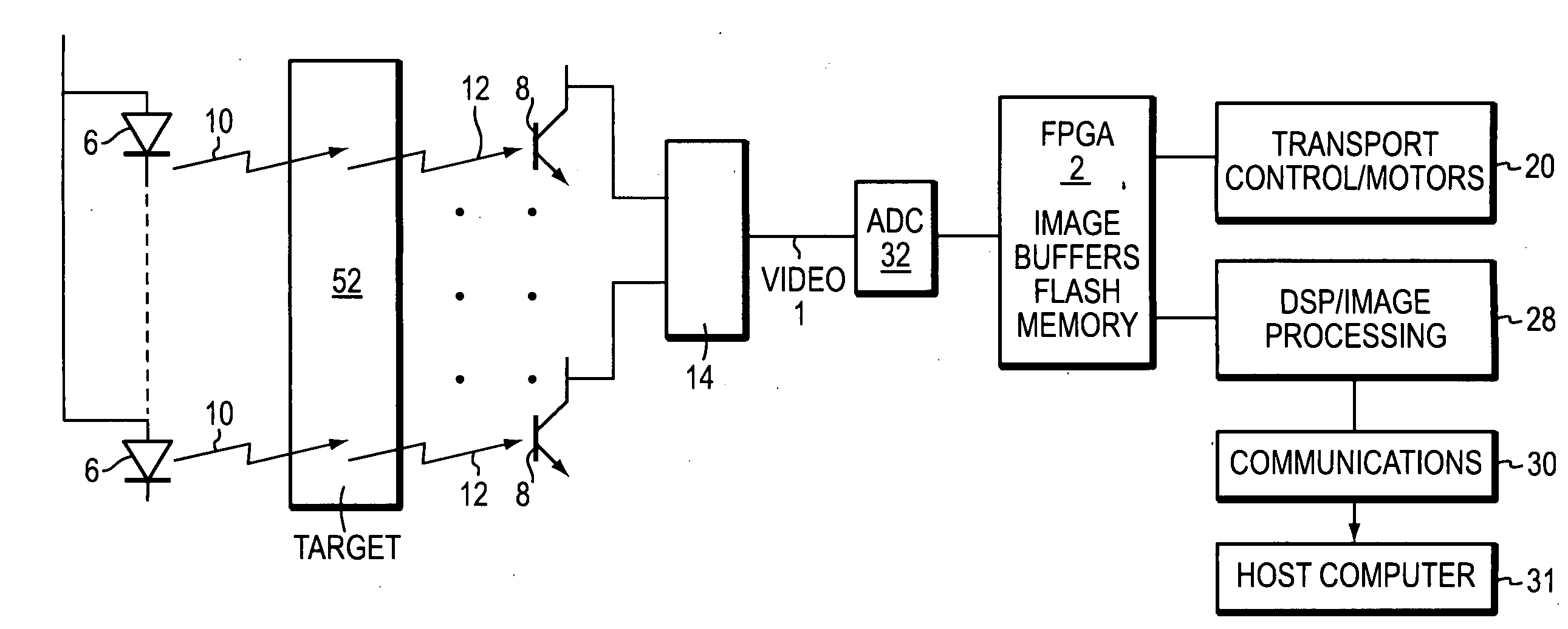
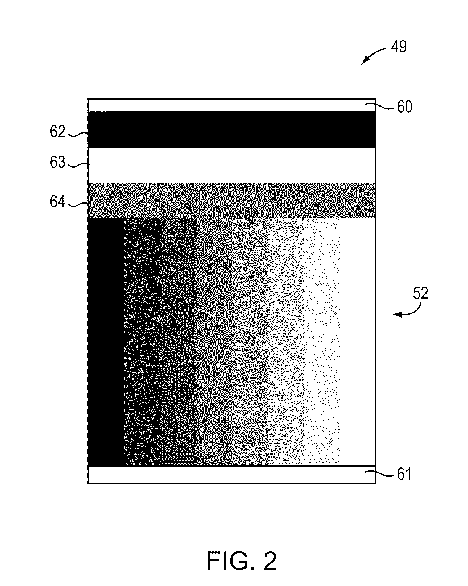
The present invention is about a system that can monitor and track the performance of an optical reader in real-time. It uses a quality factor (QF) that indicates the reader's performance quality and can alert when there are significant changes in the QF. This allows for preemptive maintenance of the reader and reduces downtime for the user. The QF is generated based on a target with a printed mid-level gray area that is scanned by the reader. The response of each pixel is measured and plotted into a histogram, which is analyzed to calculate the QF. The QF thresholds are developed over time and used to trigger maintenance visits or replacement of the reader. The QF can also be used during the final test of the reader and to inspect and accept sub-assemblies of the reader. Overall, the invention provides a tool to ensure the optimal performance of optical readers.

Problems solved by technology

Typically, once a reader is placed in the field, the manufacturer is only informed of a problem when a warranty issue or a service complaint is received.
The reader may lose calibration due to, inter alia, a change in the characteristics of the light sources and / or the photo-sensitive devices.
As a result, these service practices are slow, costly and customer unfriendly.

Method used


Image

  • Optical reader quality factor
  • Optical reader quality factor
  • Optical reader quality factor

Examples


Embodiment Construction

[0028]Restating from above, an optical reader may be calibrated to read a typical black to white gray scale dynamic range, and a particular mid-level gray area may be selected for generating a quality factor (QF). The present invention provides a system and method for calculating a QF and approving an optical reader for shipment to a user. That QF may be calculated and tracked during the service life of the reader to monitor its performance and schedule service if the QF of the reader changes over a QF standard threshold. A QF standard may be developed, over time from experience for the reader or a reader family, wherein the standard includes a triggering threshold determined from experience. Exceeding a trigger threshold may prompt the need to schedule a service call for the reader, importantly before a field failure. The present invention also may apply regardless of how the optical reader is calibrated.

[0029]Briefly, calibrating an optical reader entails balancing the optical and...


PUM


Abstract

A method and apparatus for generating and applying quality factors (QFs) to an optical reader. After an optical reader is calibrated, a mid-range gray scale level is selected and scanned. The reader outputs digital numbers (DNs) that are generated for all the pixels that will be responding to the reading of a document. A histogram of the DNs is generated and characteristics of the histogram distribution are calculated and used as QFs. For example, the standard deviation of the histogram may serve as a QF, where a lower standard deviation is preferred. Thresholds and standards may be developed from experience that indicate the operating condition of the reader. The QFs, thus, may be used during manufacturing and for field servicing of the reader.

Description

RELATED APPLICATIONS[0001]The present application is a continuation-in-part of, and claims priority from, U.S. patent application Ser. No. 12 / 342,522, which was filed on Dec. 23, 2008, and is entitled SYSTEM AND METHOD FOR CALIBRATING AN OPTICAL READER SYSTEM, and which application is of common inventorship and ownership, and which application is incorporated herein by reference.BACKGROUND OF THE INVENTION[0002]1. Field of the Invention[0003]The present invention relates to manufacturing, field service, maintenance and performance aspects of optical readers and components thereof. More particularly, the present invention relates to quality factors that may be generated for such purposes.[0004]2. Background Information[0005]Optical readers are found in many systems, including scanners, copy machines, and document readers, such as, e.g., reader systems for processing markings in an image of a form, such as a lottery playslip. Lottery playslips include, e.g., cards, tickets, and other ...

Claims


Application Information

Patent Timeline
Patent Type & Authority Applications(United States)
IPC IPC(8): G06K7/10
CPCH04N1/00002H04N1/00013H04N1/00031H04N1/00034H04N1/00045H04N1/00053H04N1/4078H04N1/00087H04N1/02865H04N1/40006H04N1/40056H04N1/401H04N1/00063
Inventor CONSTANT, JR., HENRY J.
Owner IGT GLOBAL SOLUTIONS CORP
Learn More