Objective lens drive device

Inactive Publication Date: 2010-06-24
PANASONIC CORP
View PDF4 Cites 10 Cited by
  • Summary
  • Abstract
  • Description
  • Claims
  • Application Information

AI Technical Summary

Benefits of technology

[0019]With this arrangement, the cushioning elastic body can be poured individually into the first elastic body receiving section and the second elastic body receiving section. The stable filling of the elastic body makes it possible to stabilize the frequency ch

Problems solved by technology

However, avoiding filling a cushioning member into the wire penetration hole sections reduces the range within

Method used


Image

  • Objective lens drive device
  • Objective lens drive device
  • Objective lens drive device

Examples


Example

[0030]An objective lens drive device according to the present invention will be described below on the basis of embodiments of the present invention.

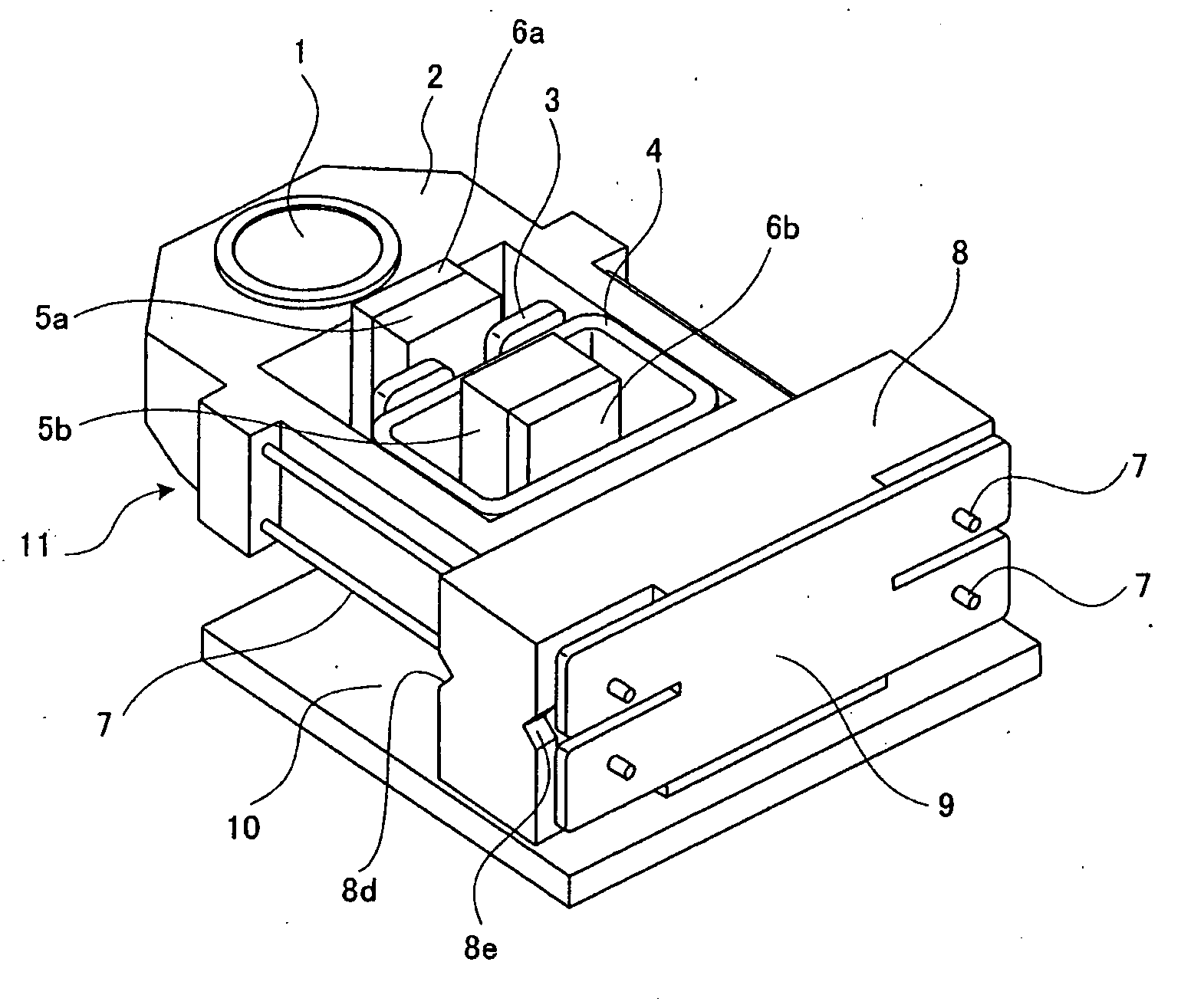
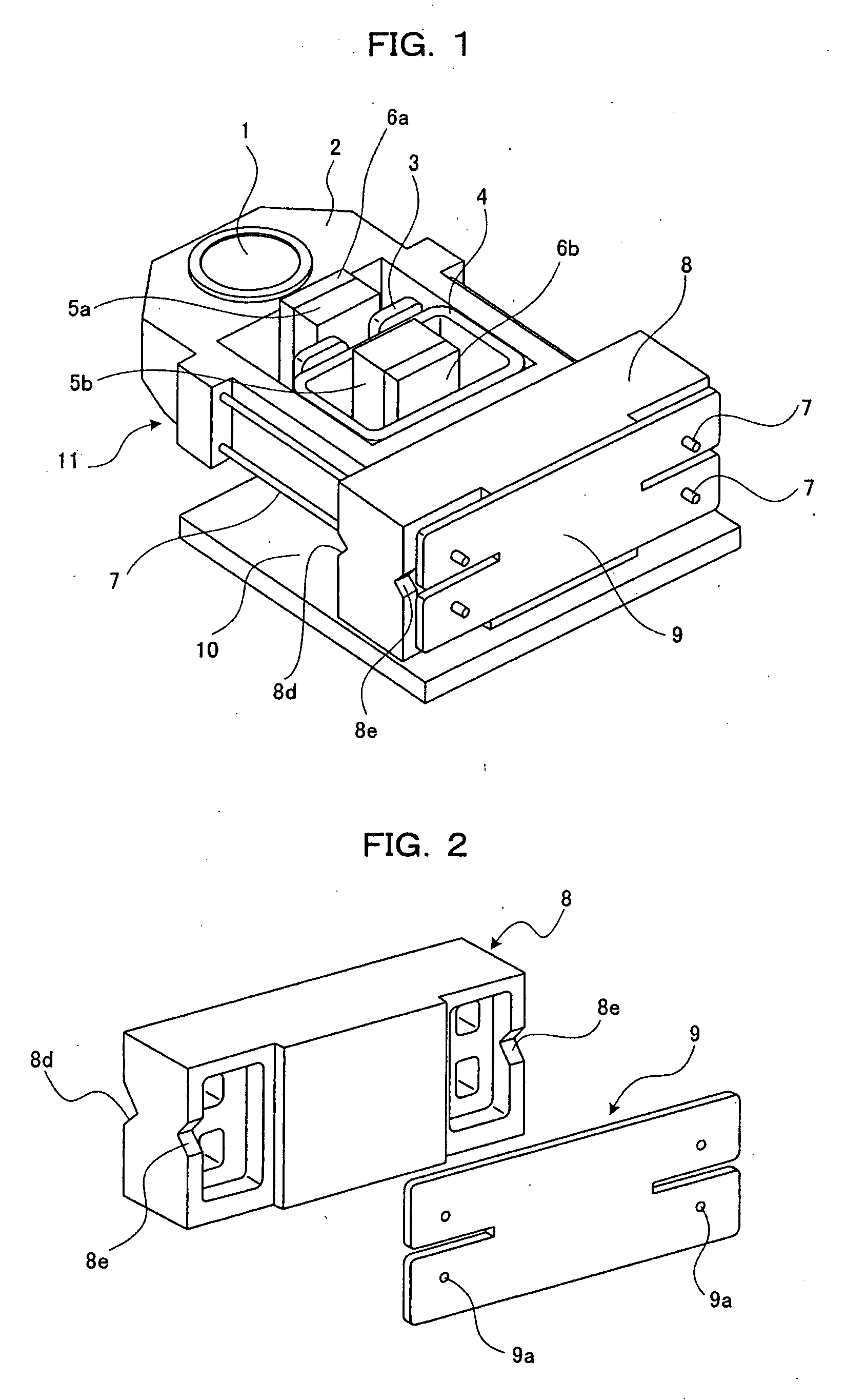
[0031]FIG. 1 is a perspective view of an objective lens drive device for an optical pickup device.

[0032]The optical pickup device is mounted in an optical disc recording and reproducing apparatus such as DVD or CD. A focusing direction corresponds to a direction at right angles to a surface of a disc. A tracking direction corresponds to a radial direction of the disc. Furthermore, a tangential direction corresponds to a direction at right angles to the focusing direction and the tracking direction. An objective lens 1 is adhesively fixed to a lens holder 2 so that the disc is irradiated with a light beam through the objective lens 1. A focusing coil 3 is made up of a coil rolled into a rectangular shape and adhesively fixed to the lens holder 2 with an axis thereof set in the focusing direction. Two tracking coils 4 are each made up of ...


PUM


Abstract

An objective lens drive device where a cushioning elastic body can be stably poured into a through-hole that is formed in a wire holder in which a suspension wire is inserted, and where the amount of the elastic body required is reduced. The through-hole that is formed in the wire holder (8) and in which the suspension wire (7) is inserted has a first elastic body receiving section (8a) formed on a lens holder (2) side, a second elastic body receiving section (8b) formed on a wire fixation member side so as to be adjacent to the first elastic body receiving section (8a), and a wire penetration hole (8c) for communicating the first elastic body receiving section (8a) and the second elastic body receiving section (8b) and having a smaller diameter than the first elastic body receiving section (8a).

Description

TECHNICAL FIELD[0001]The present invention relates to an objective lens drive device for an optical pickup device or the like provided in a DVD player and the like, and specifically, to an objective lens drive device having a lens holder suspended via a plurality of suspension wires.BACKGROUND ART[0002]In an objective lens drive device for an optical pickup device provided in a DVD player and the like, an objective lens is mounted in a lens holder. A plurality of suspension wires are fixed to the lens holder at one end of the wires and to a wire fixation member at the other end. The lens holder is thus displaceable in a focus direction at right angles to an optical disc and in a tracking direction as a radiating direction of the optical disc. Furthermore, according to Japanese Patent Laid-Open No. 7-225960 and the like, within a certain range of wires, the periphery of the wires is filled with a gel-like elastic body material to reduce the possible vibration of the wires.[0003]FIG. ...

Claims


Application Information

Patent Timeline
IPC IPC(8): G11B7/00
CPCG11B7/0932G11B7/0935G11B7/0933
Inventor IEKI, KOJIKOJIMA, HIROAKI
Owner PANASONIC CORP
Why Eureka
Try Eureka