Handover control apparatus, mobile station, base station, handover control server, and handover control method
a control apparatus and handover technology, applied in electrical devices, wireless commuication services, wireless communication, etc., can solve the problems of not always providing an optimal selection of base stations, system requires more complex communication control, etc., and achieve the above-mentioned techniques described in japanese laid-open patent publications no. 2000
- Summary
- Abstract
- Description
- Claims
- Application Information
AI Technical Summary
Benefits of technology
Problems solved by technology
Method used
Image

Examples
first embodiment
[0060]A first embodiment will now be described in detail below with reference to the accompanying drawings.
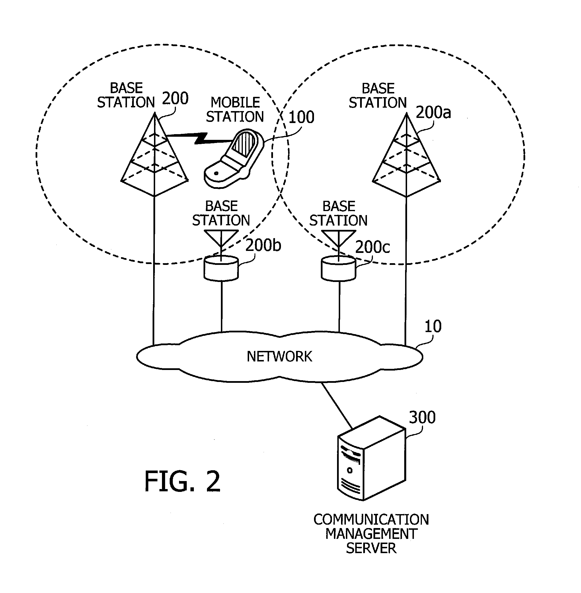
[0061]FIG. 2 illustrates a system arrangement of a communications system according to a first embodiment. The communications system of FIG. 2 is a radio communications system that permits a mobile station to communicate with another mobile station or computer via base stations. The communications system of the first embodiment is formed from a network 10, a mobile station 100, base stations 200, 200a, 200b, and 200c, and a communication management server 300. The network 10 is a wired or wireless network. The base stations 200, 200a, 200b, and 200c and communication management server 300 are connected to this network 10.
[0062]The mobile station 100 is a portable user terminal device such as mobile phone, personal digital assistant (PDA) device, and laptop computer. The mobile station 100 can communicate with a base station via radio waves when it is in the radio coverage area, ...
second embodiment
[0158]A second embodiment will now be described in detail below with reference to the accompanying drawings. The following description will focus on its difference from the foregoing first embodiment, thus omitting explanation of similar elements. The second embodiment provides a communications system which not only classifies optimal base stations into “Standby,”“Uplink,” and “Downlink,” but also evaluates them on more detailed criteria.
[0159]The system arrangement discussed in FIG. 2 for the first embodiment can similarly be used to realize a communications system according to the second embodiment. Also, the module arrangement illustrated in FIGS. 3 and 4 for the mobile station 100 and base station 200 of the first embodiment can similarly be used to realize mobile stations and base stations according to the second embodiment. The second embodiment differs from the first embodiment in how to determine candidates for the target base station for handover. The following section will...
third embodiment
[0168]A third embodiment will now be described in detail below with reference to the accompanying drawings. The following description will focus on its difference from the foregoing first embodiment, thus omitting explanation of similar elements. According to the third embodiment, optimal stations for uplink and downlink are previously determined for each individual communications system so as to permit selection of an optimal communication system at the time of handover.
[0169]The system arrangement discussed in FIG. 2 for the first embodiment can similarly be used to realize a communications system according to the third embodiment. Also, the module arrangement illustrated in FIGS. 3 and 4 for the mobile station 100 and base station 200 of the first embodiment can similarly be used to realize mobile stations and base stations according to the third embodiment. The third embodiment differs from the first embodiment in how to determine candidates for the target base station for hando...
PUM
 Abstract
Description
Claims
Application Information
 - R&D Engineer
- R&D Manager
- IP Professional
- Industry Leading Data Capabilities
- Powerful AI technology
- Patent DNA Extraction
Browse by: Latest US Patents, China's latest patents, Technical Efficacy Thesaurus, Application Domain, Technology Topic.
© 2024 PatSnap. All rights reserved.Legal|Privacy policy|Modern Slavery Act Transparency Statement|Sitemap