
Communication quality estimation method, communication quality estimation apparatus, and communication system

a communication quality and estimation method technology, applied in the field of communication quality estimation method, communication quality estimation apparatus and communication system, can solve the problems of enormous number of reception bit samples, low bit error rate, and long calculation time of bit error rate, so as to accurately determine communication quality, low bit error rate, and high bit error rate

Active Publication Date: 2006-10-31
TELECOMM ADVANCEMENT ORG OF JAPAN +2
View PDF16 Cites 84 Cited by
  • Summary
  • Abstract
  • Description
  • Claims
  • Application Information

AI Technical Summary

Benefits of technology

"The present invention provides a method and apparatus for estimating the quality of communication based on the transmission signal. This allows for quick and accurate determination of communication quality when transmitting signals using a modulation system with a high bit error rate. Additionally, the invention provides a communication system that can appropriately change over between modulation systems based on the quality of the communication. This is achieved by simulating the bit error rate or bit errors of a digital-modulated signal transmitted with a high bit error rate through the same transmission path, based on the signal point positions of a digital-modulated signal received at a low bit error rate."

Problems solved by technology

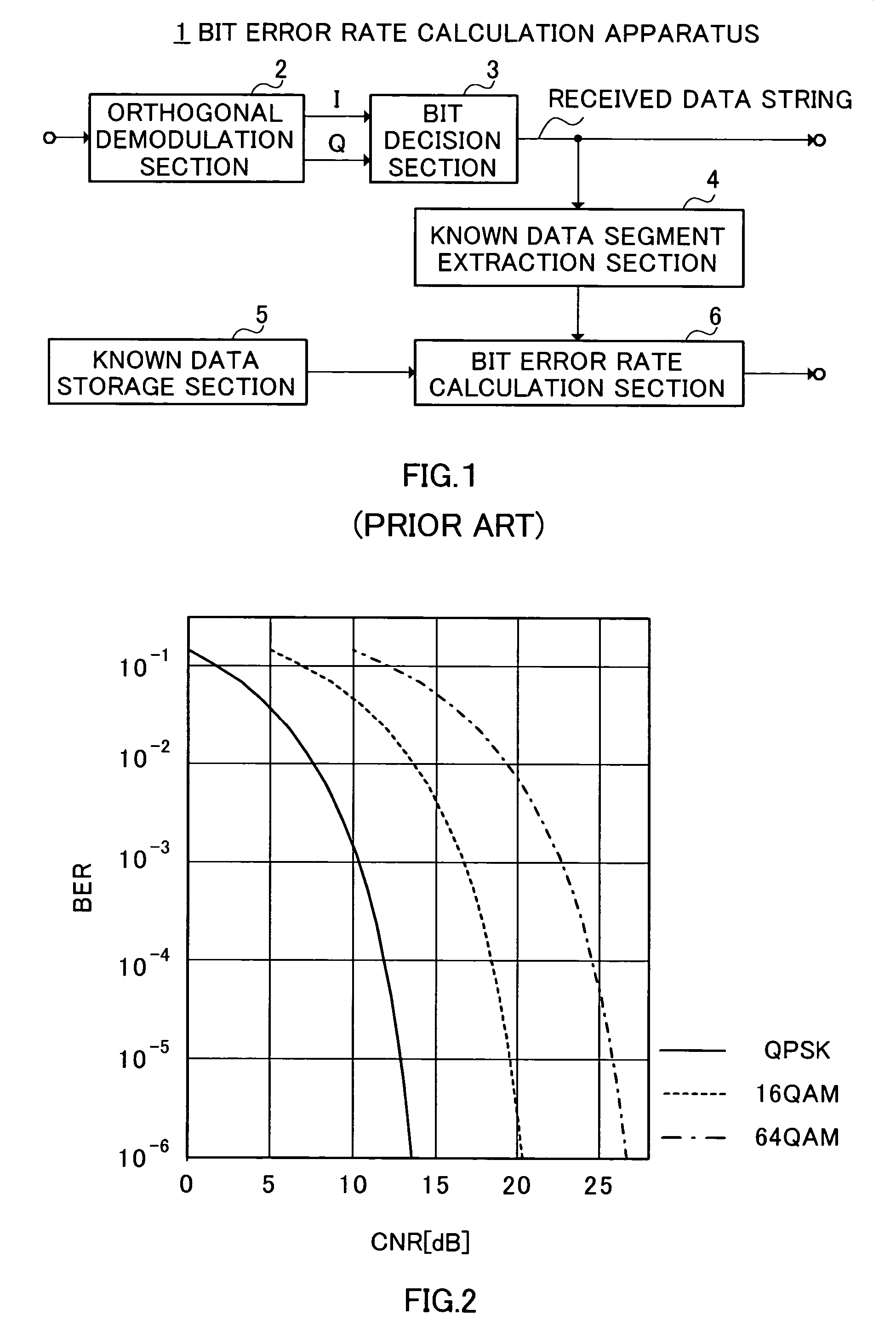
However, in a situation in which the bit error rate is low, calculating a statistically reliable bit error rate requires a sufficient total number of bits compared.
As a result, it takes a long time to calculate the bit error rate.
It takes an enormous number of reception bit samples and time for QPSK to check a bit error rate as small as 1.0E-6, and checking such a bit rate is unrealistic.
Thus, when the modulation system is changed from a modulation system such as QPSK with a relatively low bit error rate to a modulation system such as 16-value QAM with a relatively high bit error rate, there is a difficult problem in performing speedy changeover without increasing transmission errors involved in the changeover.

Method used


Image

  • Communication quality estimation method, communication quality estimation apparatus, and communication system
  • Communication quality estimation method, communication quality estimation apparatus, and communication system
  • Communication quality estimation method, communication quality estimation apparatus, and communication system

Examples


embodiment 1

(Embodiment 1)

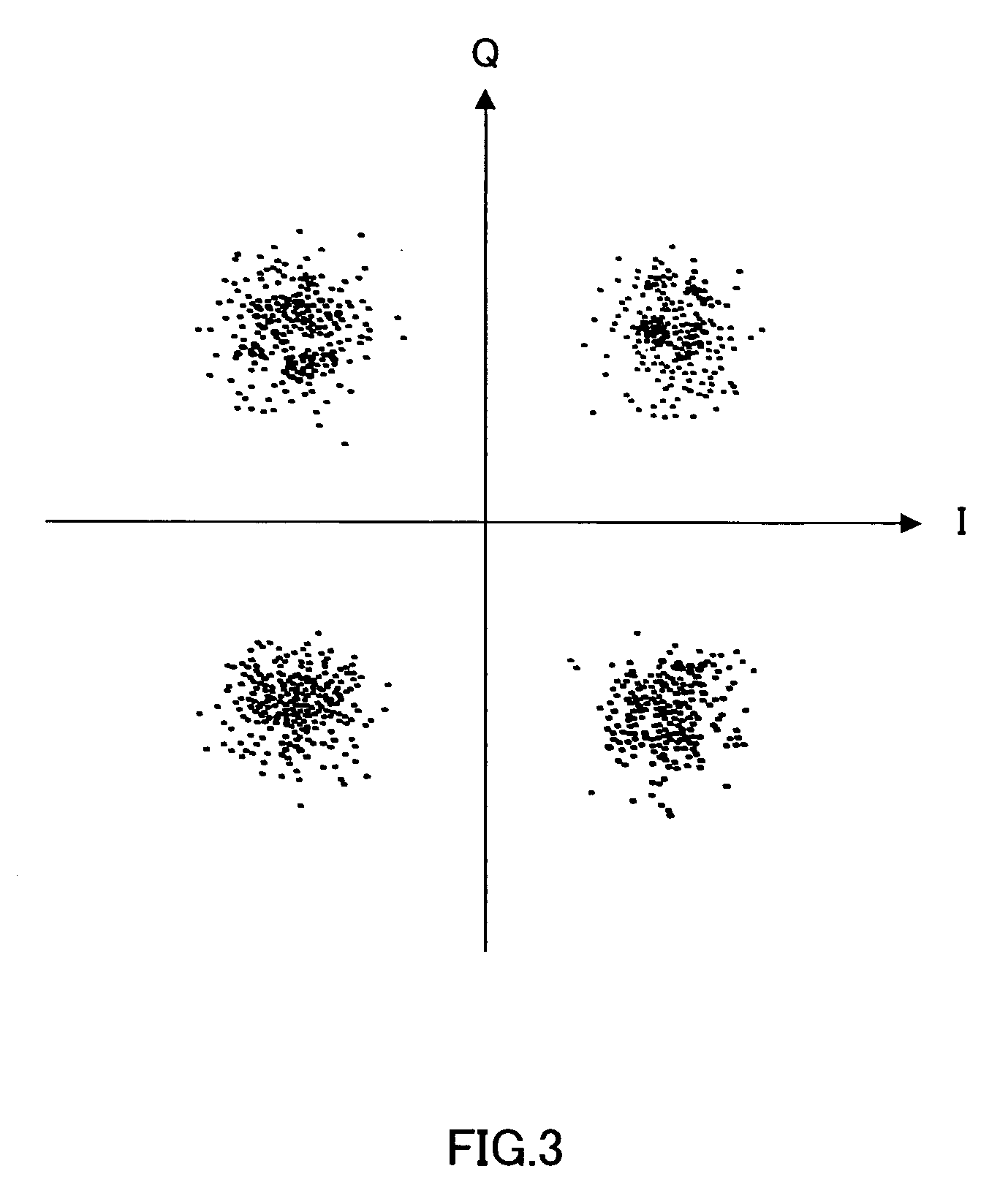
[0041]In FIG. 4, reference numeral 10 as a whole denotes a bit error rate calculation apparatus according to Embodiment 1 and inputs a QPSK modulated signal D1 to an orthogonal demodulation section 11. The orthogonal demodulation section 11 applies orthogonal demodulation processing, symbol synchronization processing and correction processing for frequency, amplitude or distortion, etc., as required to the QPSK modulated signal D1 and thereby outputs each symbol as an orthogonal IQ vector (a vector having an I and Q components on the IQ plane) signal D2. A bit decision section 12 detects the position of each received symbol on the IQ plane and thereby carries out a bit decision on the orthogonal IQ vector signal D2 of each received symbol and outputs the decided bit data string D3.

[0042]On the other hand, the bit error rate calculation apparatus 10 sends the orthogonal IQ vector signal D2 to a bit error rate estimation section 13. The bit error rate estimation section ...

embodiment 2

(Embodiment 2)

[0066]This embodiment will explain a method whereby, when a QPSK modulated signal is received, the bit error of a 64-value QAM signal with the same reception power is calculated in simulation. FIG. 10 in which the same components as those in FIG. 4 are shown with the same reference numerals assigned shows a configuration of a bit error rate calculation apparatus 20 according to Embodiment 2.

[0067]A bit error rate estimation section 23 of the bit error rate calculation apparatus 20 is designed to estimate a bit error rate of a 64-value QAM signal in simulation, assuming a 64-value QAM signal is received from an orthogonal IQ vector string of the received QPSK modulated signal D1. In this case, an average signal point detection section 25A of a threshold calculation section 25 detects an average amplitude of sequentially input IQ vectors on the IQ plane. The threshold calculation section 25B calculates a simulated threshold ths for the 64-value QAM signal based on a theo...

embodiment 3

(Embodiment 3)

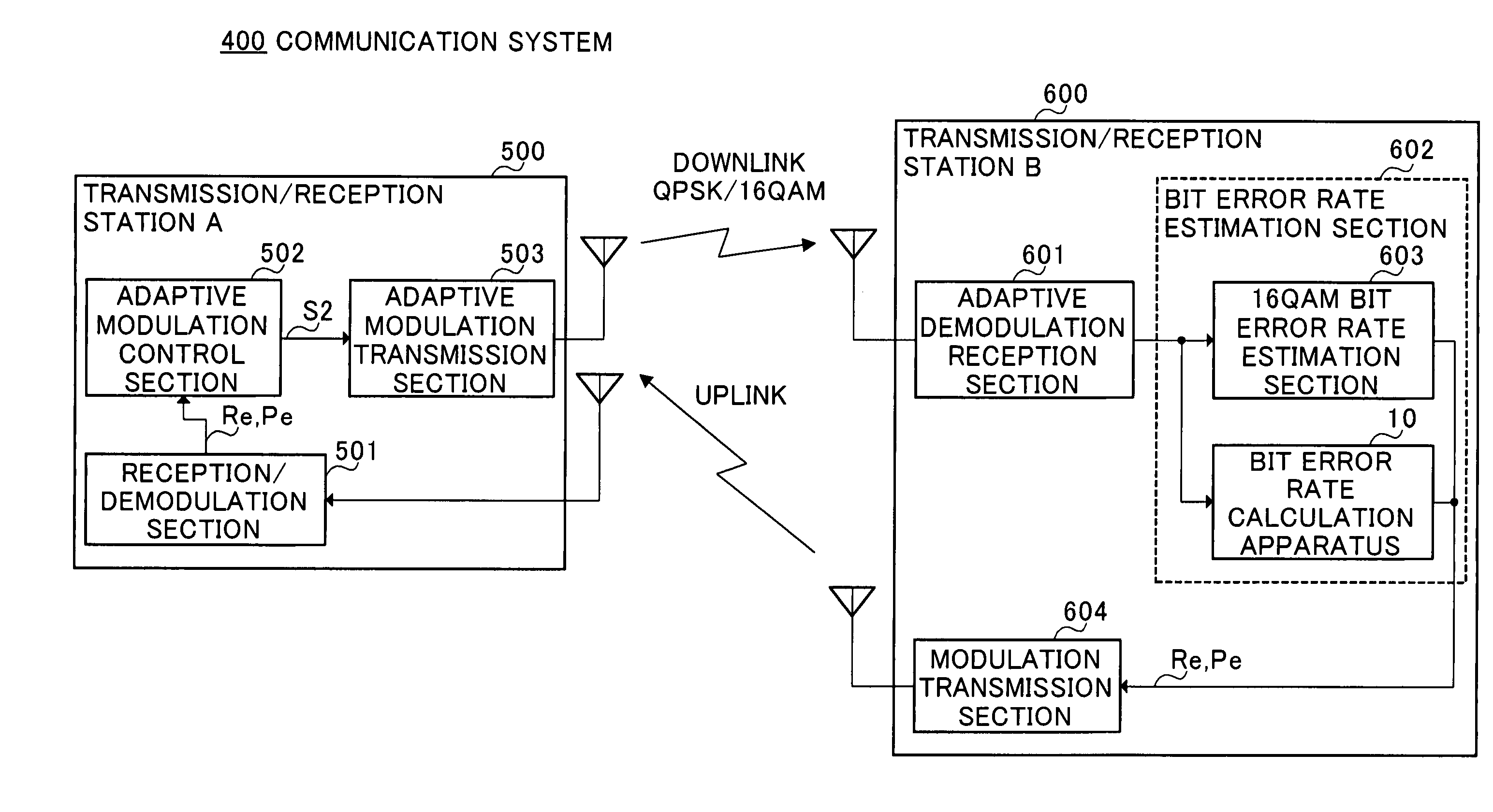
[0080]FIG. 13 shows a configuration of a communication system 100 according to Embodiment 3 in which a transmission / reception station A 200 and transmission / reception station B 300 carry out bi-directional radio communications through the same frequency channel based on a Time Division Duplex (TDD) system. In this embodiment, suppose the transmission / reception station A 200 represents a radio base station and the transmission / reception station B 300 represents a mobile terminal. Therefore, a communication link from the transmission / reception station A 200 to the transmission / reception station B 300 is a downlink and the opposite communication link is an uplink.

[0081]The communication system 100 adaptively changes its modulation system according to the quality of the communication link for the downlink and carries out a communication based on a fixed modulation system irrespective of the communication quality for the uplink. Thus, the communication system 100 can increa...


PUM


Abstract

An average signal point amplitude detection section 15A determines an average position of I and Q components when a received QPSK modulated signal is demodulated and a threshold calculation section 15B determines threshold ths on an IQ plane based on the average signal point position of the received QPSK modulated signal and a theoretical distribution position on the IQ plane of signal points of a 16-value QAM signal. Then, a threshold decision section 14A makes a threshold-decision on the I and Q components of sequentially received QPSK modulated signals using this threshold ths and thereby calculates a simulated bit error rate of the 16-value QAM signal.

Description

TECHNICAL FIELD[0001]The present invention relates to a communication quality estimation method, communication quality estimation apparatus and communication system, and is preferably used in a radio communication system using, for example, an adaptive modulation system.BACKGROUND ART[0002]Conventionally, a radio communication system performs various kinds of system control to carry out communications with high quality and high efficiency. These kinds of control include, for example, transmit power control, communication channel control, cell changeover control, etc., which improves communication quality and promotes power saving as well.[0003]Furthermore, a study on an adaptive communication system, which adaptively switches between modulation systems or between coding systems according to the communication quality of a radio communication link is also underway in recent years. For example, “Mobile Communication” (written and edited by Shuichi Sasaoka, Ohmsha, Ltd. P. 103 to 126) d...

Claims


Application Information

Patent Timeline
Patent Type & Authority Patents(United States)
IPC IPC(8): H04B17/00H04L1/00H04L1/16H04L1/18H04L1/20H04L25/06H04L27/22H04L27/34
CPCH04L1/0003H04L1/0015H04L1/0026H04L1/0034H04L1/1671H04L1/203H04L1/206H04L25/062H04L27/22H04L27/34H04L1/18
Inventor HIKOKUBO, TSUNEOABE, KATSUAKIMURAKAMI, YUTAKATAKABAYASHI, SHINICHIRO
Owner TELECOMM ADVANCEMENT ORG OF JAPAN
Learn More