
Video data processing device and video data processing method

Inactive Publication Date: 2005-06-07
SONY CORP
View PDF3 Cites 30 Cited by
  • Summary
  • Abstract
  • Description
  • Claims
  • Application Information

AI Technical Summary

Benefits of technology

[0010]In view of the above identified problem, it is therefore the object of the present invention to provide a video data processing device and a video data processing method that can improve the quality of output images if compared with conventional apparatus and methods.
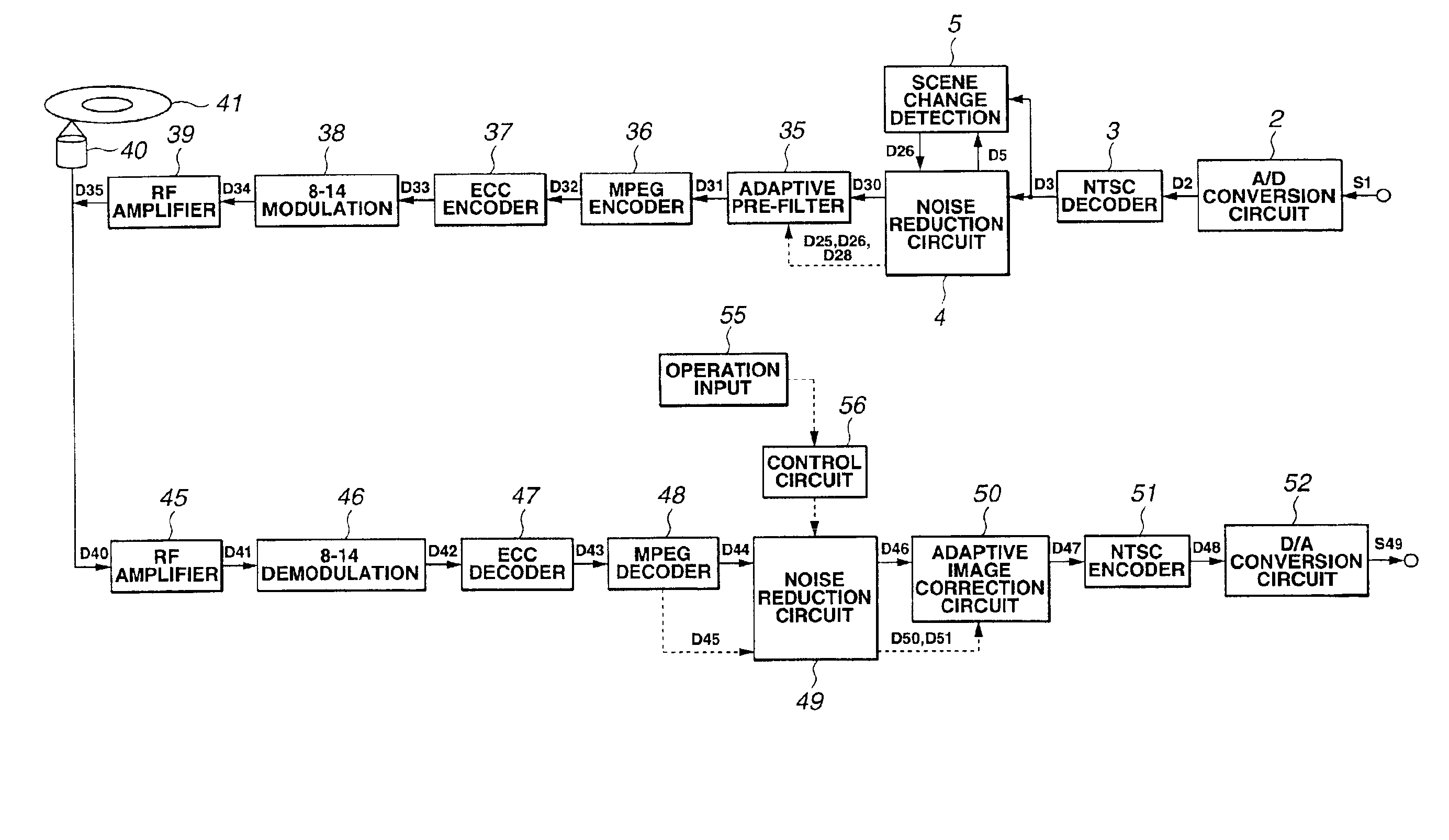
[0011]According to the invention, the above object is achieved by adaptively filtering video data at the time of coding as a function of the degree of difficulty of coding and adaptively compensating the video data after the decoding processing step as a function of the degree of difficulty of coding of the video data in order to reduce the coding noise and adequately correct the image quality.
[0026]Thus, according to the invention, the coding noise can be reduced by adaptively filtering video data at the time of coding as a function of the degree of difficulty of coding and the image quality can be adequately corrected by adaptively compensating the video data after the decoding processing step as a function of the degree of difficulty of coding of the video data. Additionally, the amount of information can be effectively reduced by adaptively filtering the video data, using the degree of coding difficulty of the entire image and that of each of selected local areas of the image.
[0027]Therefore, according to the invention, there are provided a video data processing device and a video data processing method that can improve the quality of output images if compared with conventional apparatus and methods.

Problems solved by technology

Therefore, if the operation of compensating the reduced volume of the high frequency component is conducted uniformly after the decoding processing step, some of the images to be compensated can be compensated inadequately.

Method used


Image

  • Video data processing device and video data processing method
  • Video data processing device and video data processing method
  • Video data processing device and video data processing method

Examples


Embodiment Construction

[0044]Now, the present invention will be described by referring to the accompanying drawing that illustrate preferred embodiments of the invention.

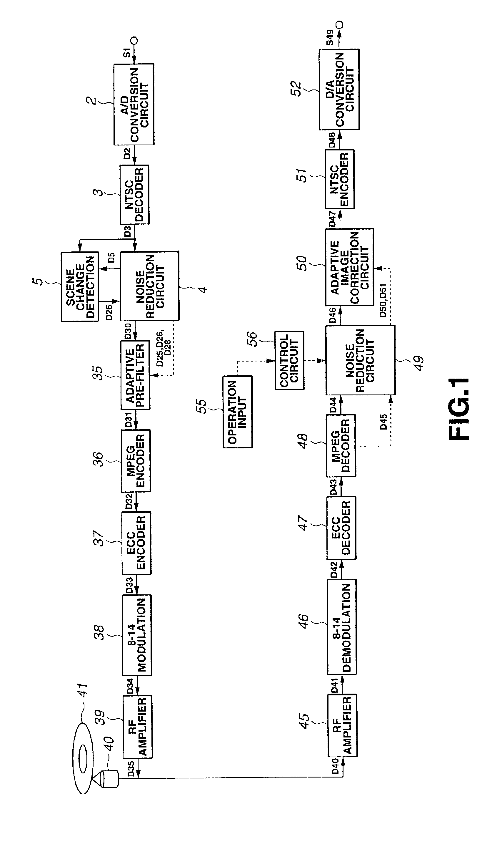
[0045]The present invention is typically applied to a recording / reproduction apparatus 1 having a configuration as shown in the block diagram of FIG. 1.

[0046]Referring to FIG. 1, this recording / reproduction apparatus 1 is so designed as to receiving an NTSC(National Television System Committee) video signal S1 from the outside through analog / digital (A / D) conversion circuit 2 and then the video data D2 obtained by the A / D conversion of the A / D conversion circuit 2 is sent out from the A / D conversion circuit 2 to NTSC decoder 3. The NTSC decoder 3 separates the luminance signal and the color signal of the NTSC video data D2 from each other and transmits the video data D3 including the luminance signal and the color signal that are separated from each other to noise reduction circuit 4 and scene change detection circuit 5.

[0047]Referring no...


PUM


Abstract

The image quality of video data is remarkably improved by a video data processing device and a video data processing method according to the invention. The input video data is adaptively filtered by adaptive filter 35 at the time coding as a function of the degree of coding difficulty of image and the decoded video data is adaptively compensated by adaptive image quality correcting circuit 50 as a function of the degree of coding difficulty of image to reduce the coding noise and appropriately correct the image quality.

Description

BACKGROUND OF THE INVENTION[0001]1. Field of the Invention[0002]This invention relates to a video data processing device and a video data processing method that can suitably be used for a recording / reproduction apparatus adapted to compression-coding input video data and recording them on an optical disc.[0003]2. Related Background Art[0004]Compression-coding conforming to the MPEG (Moving Picture Experts Group) Standard is known. With compression-coding conforming to the MPEG Standard, the amount of video data to be handled is reduced by utilizing spatial correlations of data in a same frame and temporal correlations of data in different frames.[0005]Therefore, the recording / reproduction apparatus using a coding system conforming to the MPEG Standard compression-codes the input video data to generate compression-coded video data and record them on an optical disc. For data reproduction, the recording / reproduction apparatus reproduces the compression-coded data from the optical disc...

Claims


Application Information

Patent Timeline
IPC IPC(8): H04N7/36H04N7/26H04N9/804H04N5/85H04N5/84H03M7/38H04N19/117H04N19/137H04N19/142H04N19/176H04N19/189H04N19/50H04N19/51H04N19/527H04N19/625H04N19/65H04N19/80H04N19/85H04N19/86H04N19/89
CPCH04N19/80H04N19/51H04N9/8042H04N5/85H04N5/781
Inventor KOBAYASHI, HIROSHIFUKUDA, KYOKOTOMITA, MASAMIMIYATA, KATSUNARI
Owner SONY CORP
Learn More