
Techniques for transmission of sounding reference signal in shared radio frequency spectrum band

a technology of sounding reference signal and radio frequency spectrum, which is applied in the direction of digital transmission, power management, transmission path sub-channel allocation, etc., can solve the problems of further reducing devices may not win contention for access to the carrier, etc., to reduce the transmission opportunity of srs of a ue, increase the likelihood of srs transmission, and enhance network efficiency

Active Publication Date: 2017-07-06
QUALCOMM INC
View PDF3 Cites 27 Cited by
  • Summary
  • Abstract
  • Description
  • Claims
  • Application Information

AI Technical Summary

Benefits of technology

This patent relates to improving wireless communication by transmitting a sounding reference signal (SRS) in a shared RF spectrum band and a dedicated RF spectrum band. The current techniques used for SRS transmissions in LTE and LTE-Advanced systems may result in the UE dropping the SRS transmission when power limited or if there is a conflict with a PUSCH or PUSCH transmission. This may reduce the efficiency of the network. The techniques provided in the disclosure may increase the likelihood of transmitting the SRS, improve network efficiency, and provide more accurate channel quality information for setting transmission parameters. Additionally, a higher priority may be assigned to the SRS transmission in the shared RF spectrum band as compared to a similar transmission in a dedicated RF spectrum band. The techniques may also involve using a different set of downlink and uplink CCs for SRS transmission.

Problems solved by technology

For some radio frames, a device of a PLMN may win contention for access to a carrier in the shared RF spectrum band, while for other radio frames, the device may not win contention for access to the carrier in the shared RF spectrum band.
Additionally, when using a shared RF spectrum band a UE may not win contention for a wireless transmission, which may further reduce SRS transmission opportunities of a UE.

Method used


Image

  • Techniques for transmission of sounding reference signal in shared radio frequency spectrum band
  • Techniques for transmission of sounding reference signal in shared radio frequency spectrum band
  • Techniques for transmission of sounding reference signal in shared radio frequency spectrum band

Examples


Embodiment Construction

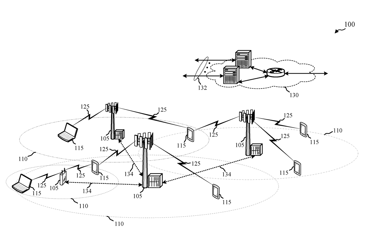
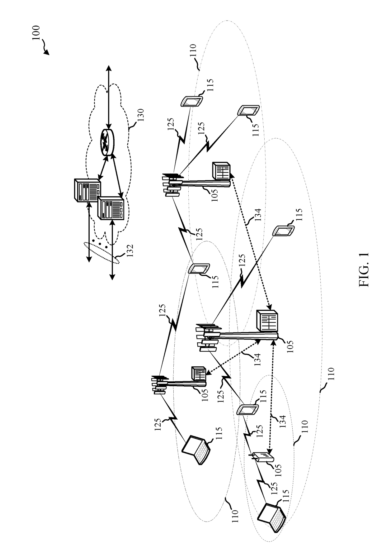
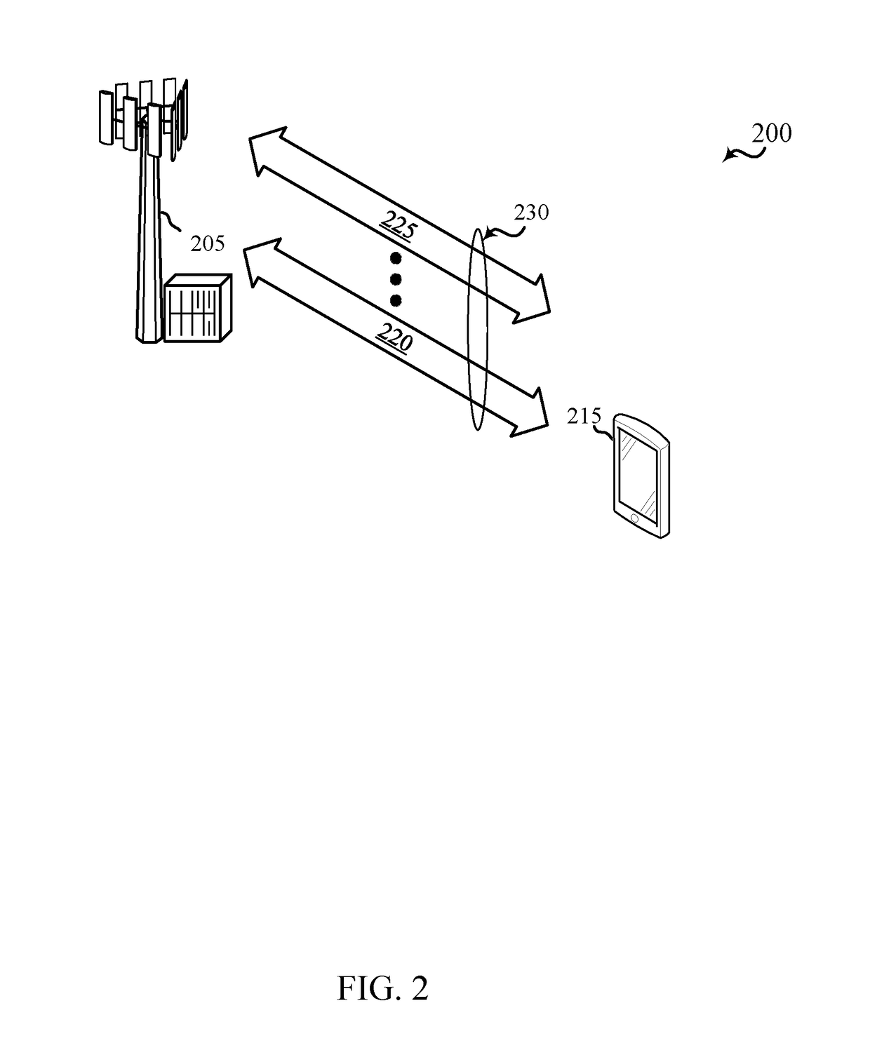
[0045]Techniques are described in which a shared radio frequency (RF) spectrum band is used for at least a portion of communications over a wireless communication system. In some examples, the shared RF spectrum band may be used for LTE / LTE-A communications and may be used to transmit a sounding reference signal (SRS) by a user equipment (UE). The shared RF spectrum band may be used in combination with, or independent from, a dedicated RF spectrum band. The dedicated RF spectrum band may include a RF spectrum band for which transmitting apparatuses may not contend for access (e.g., a RF spectrum band licensed to particular users for particular uses, such as a licensed RF spectrum band usable for LTE / LTE-A communications). The shared RF spectrum band may include a RF spectrum band for which transmitting apparatuses may contend for access (e.g., a RF spectrum band that is available for unlicensed use, such as Wi-Fi use, a RF spectrum band that is available for use by different radio a...


PUM


Abstract

Sounding reference signal (SRS) transmissions in a shared RF spectrum band, alone or in conjunction with a dedicated RF spectrum band, may be transmitted using two or more uplink component carriers (CCs). A UE may identify that the two or more CCs are in a same timing advance group (TAG), and transmit a SRS transmission and a physical uplink shared channel (PUSCH) or physical uplink control channel (PUCCH) transmission during a same uplink symbol. A UE may transmit a SRS based on a minimum configured power in the event that the UE is power limited during a SRS transmission symbol. A channel priority assigned to a CC carrying a SRS transmission in a shared RF spectrum band may be set to a higher channel priority than a channel priority for a similar transmission using a dedicated RF spectrum band.

Description

CROSS REFERENCES[0001]The present Application for Patent claims priority to U.S. Provisional Patent Application No. 62 / 273,294 by Chen, et al., entitled “Techniques For Transmission of Sounding Reference Signal in Shared Radio Frequency Spectrum Band,” filed Dec. 30, 2015, assigned to the assignee hereof.BACKGROUND[0002]Field of the Disclosure[0003]The present disclosure, for example, relates to wireless communication systems, and more particularly to techniques for transmission of sounding reference signals in a shared radio frequency (RF) spectrum band and a dedicated RF spectrum band.[0004]Description of Related Art[0005]Wireless communication systems are widely deployed to provide various types of communication content such as voice, video, packet data, messaging, broadcast, and so on. These systems may be multiple-access systems capable of supporting communication with multiple users by sharing the available system resources (e.g., time, frequency, and power). Examples of such ...

Claims


Application Information

Patent Timeline
Patent Type & Authority Applications(United States)
IPC IPC(8): H04W16/14H04W72/04H04W52/30H04L5/00
CPCH04W16/14H04L5/0048H04W52/30H04W72/0446H04W72/0453H04W72/0413H04L5/001H04W72/21
Inventor CHEN, WANSHIGAAL, PETER
Owner QUALCOMM INC
Learn More