
Control unit and display unit for an emg controlled ventilator

Active Publication Date: 2010-07-22
MAQUET CRITICAL CARE
View PDF9 Cites 25 Cited by
  • Summary
  • Abstract
  • Description
  • Claims
  • Application Information

AI Technical Summary

Benefits of technology

[0013]This provides an improved user interface for the operator of an EMG controlled ventilator, which will enable faster and more reliable determination of the correct position of the esophageal catheter within the patient.

Problems solved by technology

Such a signal from an esophageal catheter is prone to disturbances from other myoelectrical signals that are present in the patient's body.
A problem when obtaining a myoelectrical signal from the diaphragm is positioning of the catheter within the patient's esophagus.
There is a possibility that the catheter will be inserted too far, or not be inserted far enough.
In both cases the catheter will detect a weak signal or may not capture any signal at all.
Hence, it is difficult to obtain an optimal catheter position and the ventilator may have to work in pneumatic triggering mode if the signal is too weak.
Hence, even if the esophageal catheter is placed correctly initially, it may move in such a way that it no longer records the EMG signal of the diaphragm.
There is also a risk that the catheter will be moved inadvertently, to be inserted too far into the patient or be pulled out from the patient's esophagus.

Method used


Image

  • Control unit and display unit for an emg controlled ventilator
  • Control unit and display unit for an emg controlled ventilator
  • Control unit and display unit for an emg controlled ventilator

Examples


Embodiment Construction

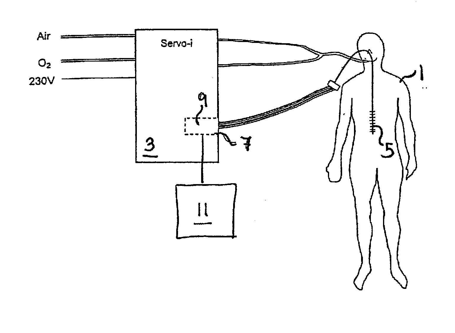
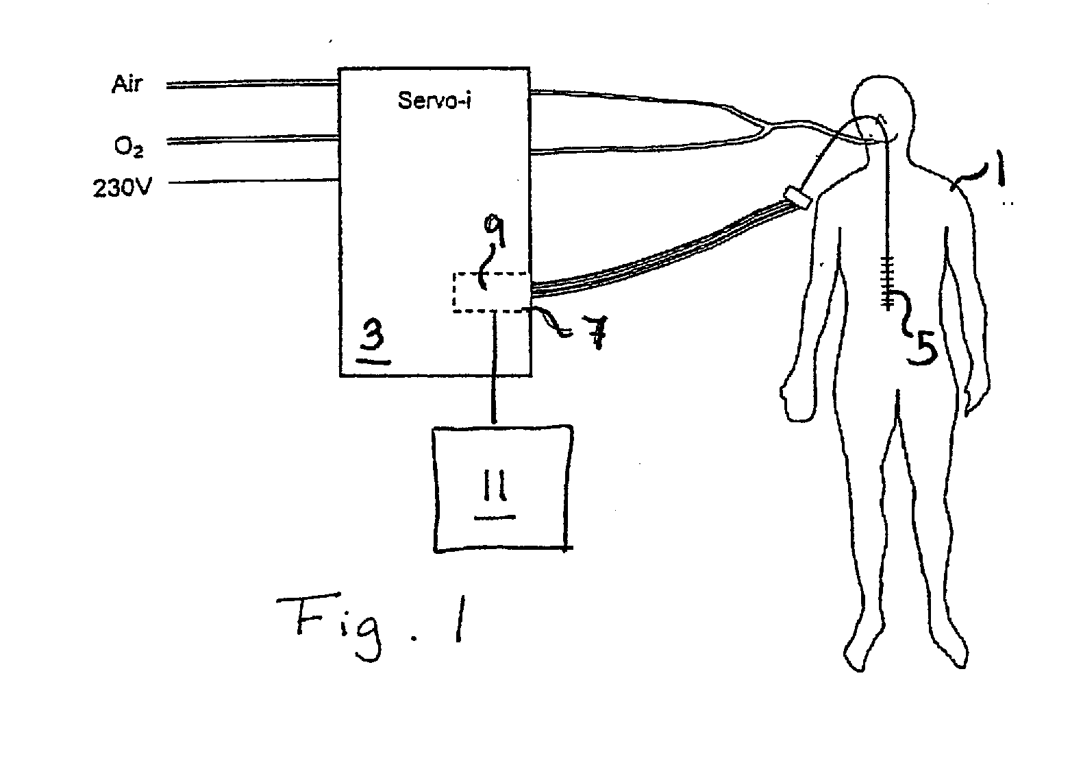
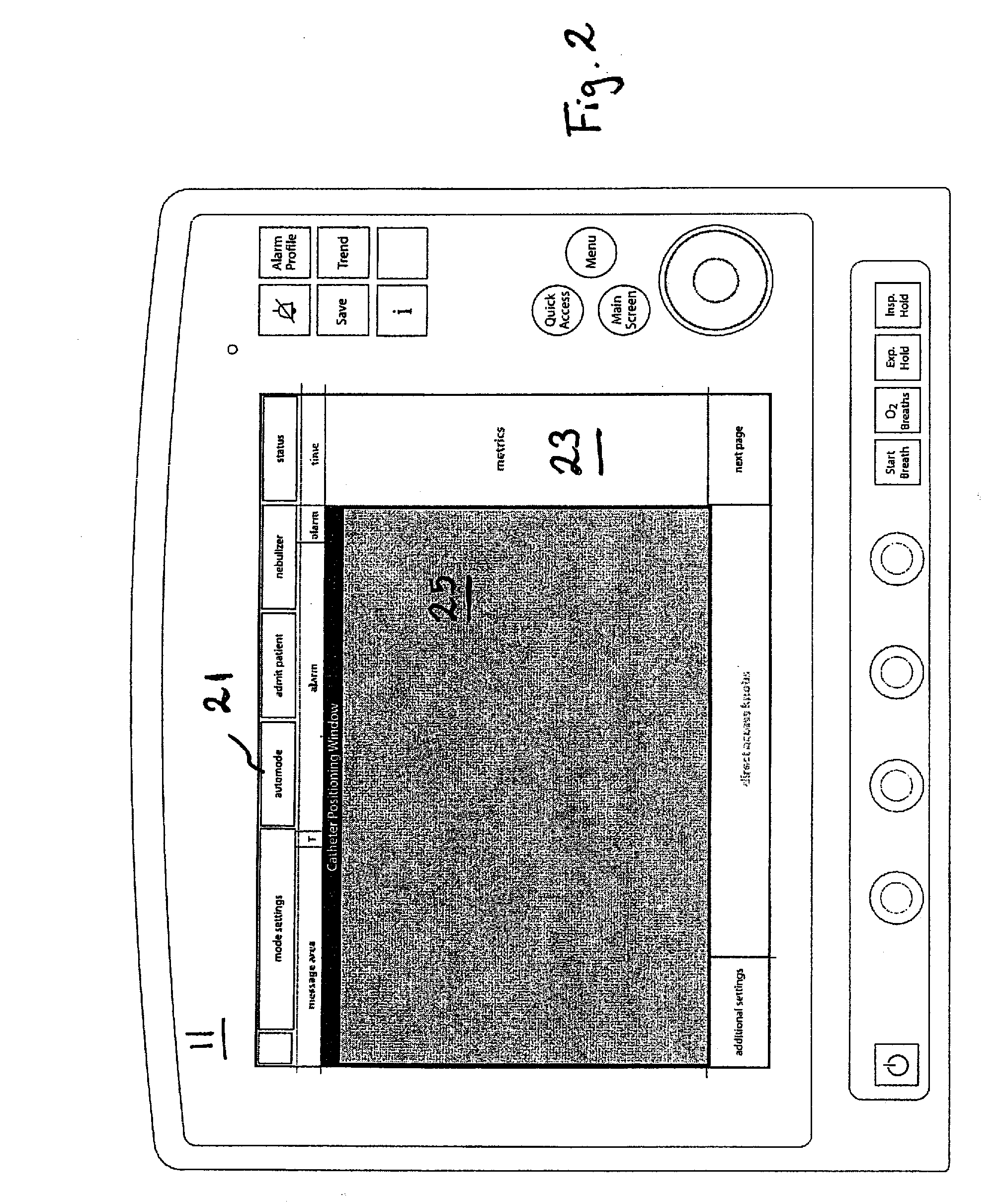
[0023]FIG. 1 is a schematic overview of a patient 1 connected to a ventilator 3 and having an esophageal catheter 5 inserted in order to record a myoelectric signal from the diaphragm. This myoelectric signal is fed to a control input 7 of the ventilator 3 to control the ventilating function of the patient 1. The catheter 5 carries a number of electrodes, for example, nine electrodes placed equidistantly in an array along the catheter to produce 8 subsignals, each subsignal being a difference signal between two neighbouring electrodes, that is, the signal from an electrode pair. The subsignals will be processed in a control unit 9 in the ventilator to produce the overall signal that can be used to control the ventilator. To this end the control unit 9 selects the signal or signals from the electrode pairs that best represent the EMG signal. How to do this is disclosed in detail in U.S. Pat. No. 5,671,752 and WO2005 / 048838. The control unit 9 also controls a display unit 11 having at...


PUM


Abstract

A control unit for controlling a ventilator that provides EMG controlled ventilation to a patient receives EMG signals from an esophageal catheter inserted into the patient and selects, dependent on the EMG signal, at least one signal for controlling the ventilator. A user interface unit operates by the control unit indicates the position of the catheter relative to the patient's diaphragm based on the selected signal. The position information may be presented in relation to signal curves representing the catheter signal or as an elongate vertical shape representing the catheter, the display unit being operated to indicate on the elongate vertical shape the position of the diaphragm.

Description

BACKGROUND OF THE INVENTION1. Field of the Invention[0001]The present invention relates to a control unit and a display unit for an EMG controlled ventilator.[0002]2. Description of the Prior Art[0003]U.S. Pat. No. 5,671,752 discloses a method and a device for registering the myoelectrical activity of the diaphragm by means of an esophageal catheter having an array of electrodes. Such a signal from an esophageal catheter is prone to disturbances from other myoelectrical signals that are present in the patient's body. For improving the signal-to-noise ratio of such an electromyographic signal cross-correlation of the signals from the different electrodes in the catheter is used. Electrode pairs on opposite sides of the diaphragm but having approximately the same distance to the diaphragm will produce signals that are opposite but substantially equal in magnitude and phase. By subtracting the signals from one electrode pair from the other the two desired signals will be added, while t...

Claims


Application Information

Patent Timeline
IPC IPC(8): A61M16/00
CPCA61B5/04884A61B5/06A61M16/0051A61M16/12A61M2205/3331A61M2205/502A61M2205/584A61M2230/60A61M2210/1014A61M2210/105A61M2230/08A61M2230/005A61B5/065A61M16/024A61B5/392
Inventor BLOMQUIST, KARINJALDE, FREDRIK
Owner MAQUET CRITICAL CARE
Learn More