Method for manufacturing and transport of a generator stator core

Inactive Publication Date: 2010-07-29
ALSTOM TECH LTD
View PDF13 Cites 1 Cited by
  • Summary
  • Abstract
  • Description
  • Claims
  • Application Information

AI Technical Summary

Benefits of technology

[0017]No suggestions are made in the state of the art to make vertical stacking simpler. US 2005/0235480 A1 even explicitly mentions the need to stack the stator core horizontally instead of vertically. The state of the art only offers improved methods for horizontal assembly of the stator core, e.g. by using key bar extensions, while US 2005/0236926 A1 discloses a central rail structure extending through the centre axis of the stator frame, aiding in th

Problems solved by technology

If the manufacturing does not take place at the final installation site, which is difficult, because all manufacturing machinery would have to be transferred to every installation site, the final assembly of stator core within the frame has to be transported to said final installation site, e.g. on railway wagons.
This is only possible for stator c

Method used


Image

  • Method for manufacturing and transport of a generator stator core
  • Method for manufacturing and transport of a generator stator core
  • Method for manufacturing and transport of a generator stator core

Examples


Embodiment Construction

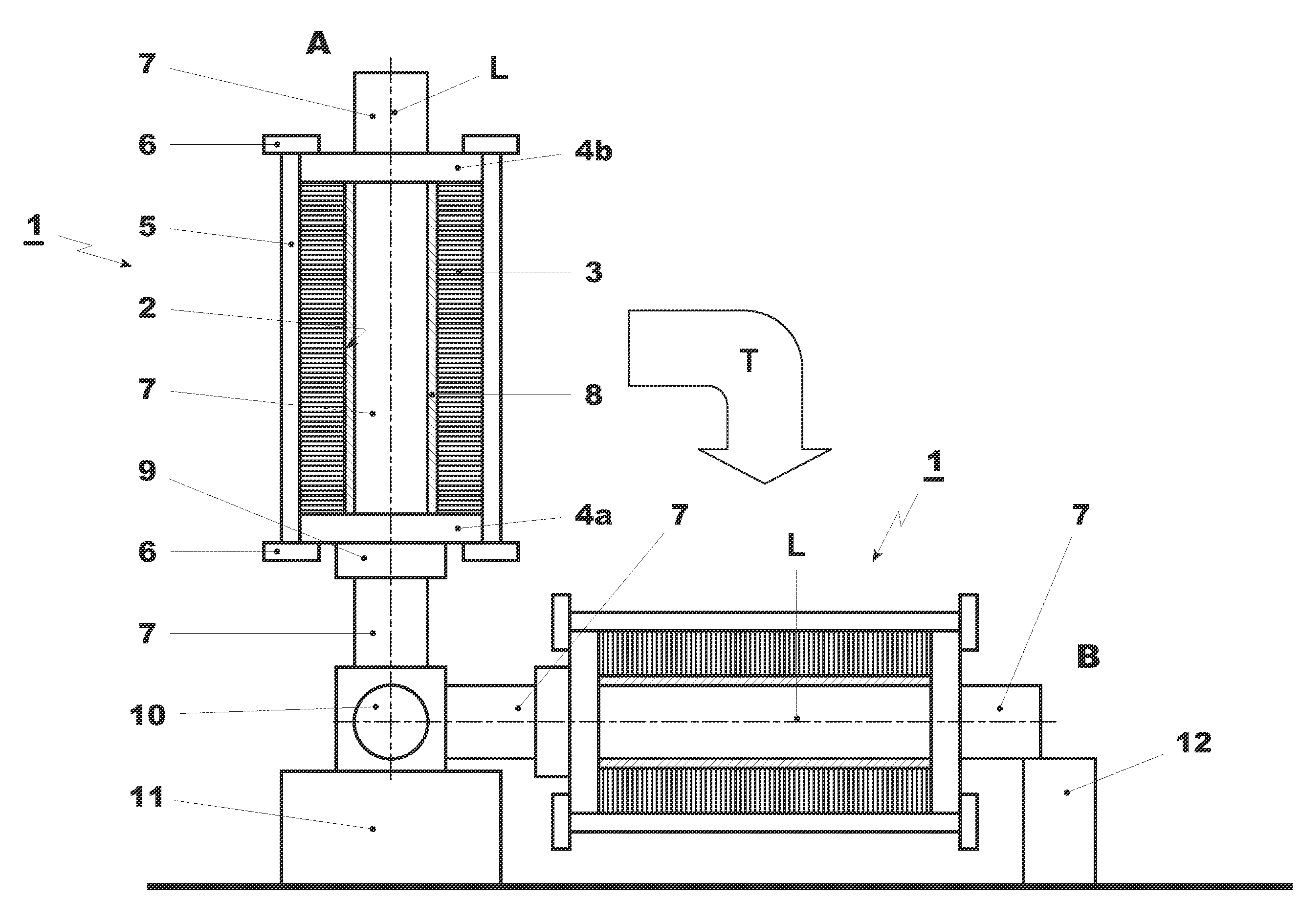
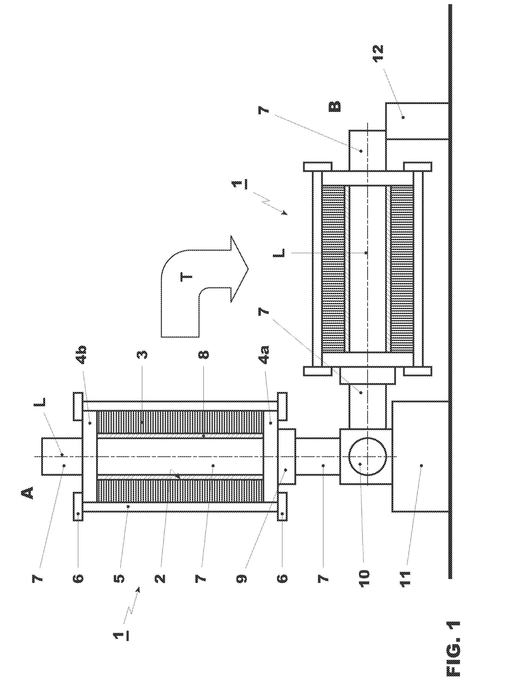
[0034]Referring to the drawings, which are for the purpose of illustrating the present preferred embodiments of the invention and not for the purpose of limiting the same, FIG. 1 shows, on the left, a stator core 1 in vertical position A after stacking. On the right hand side, a stator core is shown in a horizontal position B following toppling T. In its horizontal position after stacking and toppling, the stator core 1 is ready for winding and / or handling and / or transport to a different location. The stator core 1 itself is shown as an axial cut, whereas the other elements are shown schematically.

[0035]A stator core I, which has a central cylindrical bore 2, namely a through bore, generally comprises a stack of laminations 3. With respect to the stator core 1 of FIG. 1, the stacking step is performed vertically along a longitudinal axis A, which extends perpendicular to the plane of the ground 16.

[0036]According to the method depicted in FIG. 1, manufacturing of the stator core I b...


PUM

PropertyMeasurementUnit
Weightaaaaaaaaaa
Weightaaaaaaaaaa
Diameteraaaaaaaaaa

Abstract

A method for manufacturing and preparing for assembly a stator core of a generator, the stator core having a central cylindrical bore along a longitudinal axis of the stator core, the method including in a first step, mounting a first press plate onto a tooling device and concomitantly and/or subsequently positioning at least one key bar to be manufactured in an axial direction with respect to the longitudinal axis in a spaced manner along a peripheral circumference of the first press plate. The method includes in a second step, stacking a plurality of generator laminations onto the first press plate and mechanically coupling the plurality of generator laminations with the at least one key bar and, in a third step, mounting a second press plate onto the plurality of generator laminations, fixing the second press plate to at least one of the at least one key bar and at least one axial fixing device and concomitantly and/or subsequently exerting axial stress on the first and the second press plates.

Description

[0001]Priority is claimed to European Patent Application No. EP 08172143,3, filed Dec. 18, 2008, the entire disclosure of which is incorporated by reference herein.[0002]The present invention relates to the manufacture of electrical generators, and more specifically to the assembly of stator cores of such generators.BACKGROUND[0003]In the power generation industry, generator stator cores are supported on mounting frames. In preferred constructions, as mentioned in US 2007 / 0241629 A1, the stator core is formed from a plurality of stacked laminations, preferably thin steel laminations which are stacked, pressed and clamped together into the large cylindrical form of the stator core. Stacking can take place in a vertical or horizontal position of the stator core. Vertical stacking makes use of gravity to aid in the placement of the laminations. However, after vertical stacking, the stack has to be transferred to a horizontal position for further handling. In case of horizontal stacking...

Claims


Application Information

Patent Timeline
IPC IPC(8): H02K1/18H02K15/02
CPCH02K1/16H02K1/185H02K15/028Y10T29/5137Y10T29/49078Y10T29/49009H02K15/16
Inventor VERRIER, MICHEL
Owner ALSTOM TECH LTD
Why Eureka
Try Eureka