Microphone having rear phase rejection collection tube

Inactive Publication Date: 2010-08-19
HEIL SOUND
View PDF1 Cites 28 Cited by
  • Summary
  • Abstract
  • Description
  • Claims
  • Application Information

AI Technical Summary

Problems solved by technology

The desired and undesired acoustical signals entering the front ap

Method used


Image

  • Microphone having rear phase rejection collection tube
  • Microphone having rear phase rejection collection tube
  • Microphone having rear phase rejection collection tube

Examples


Embodiment Construction

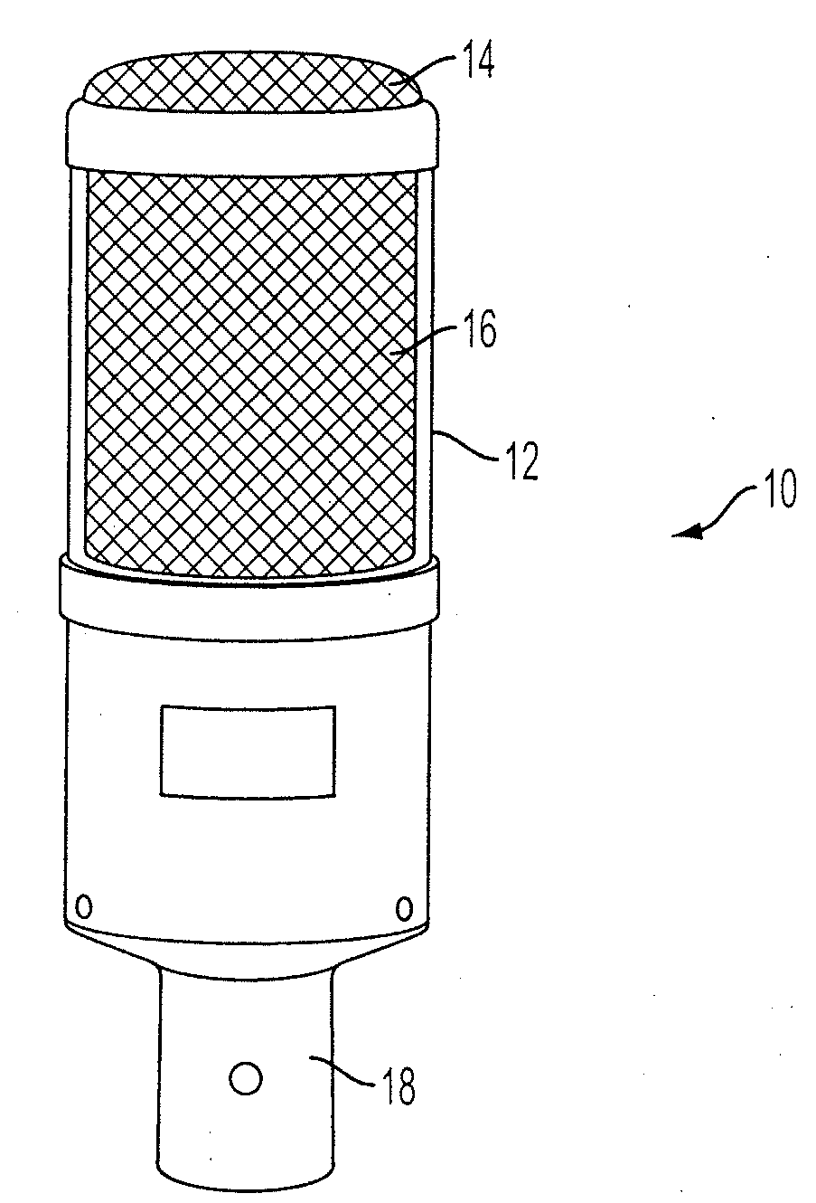
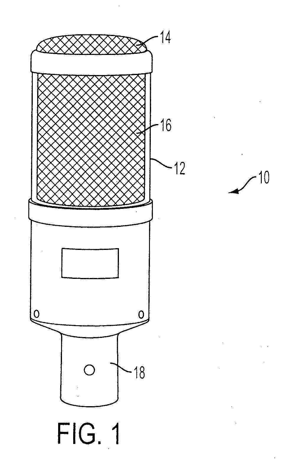
[0013]Referring to FIG. 1, the microphone 10 includes a hollow outer tubular shell 12 formed in a cylindrical shape. The shell 12 has front apertures 14 located on its top end and side apertures 16 substantially circumferentially surrounding the shell 12. The apertures 14 and 16 are designed to allow acoustical signals to flow into the interior of the tubular shell 12 for processing and possible amplification by the microphone 10. The apertures 14 and 16 may be formed from mesh screening, for example an inner and outer layer of mesh screening, with the outer layer having larger openings than the inner layer. The tubular shell 12 may be attached to a microphone base 18, which may act as a handle and typically houses the microphone cord.

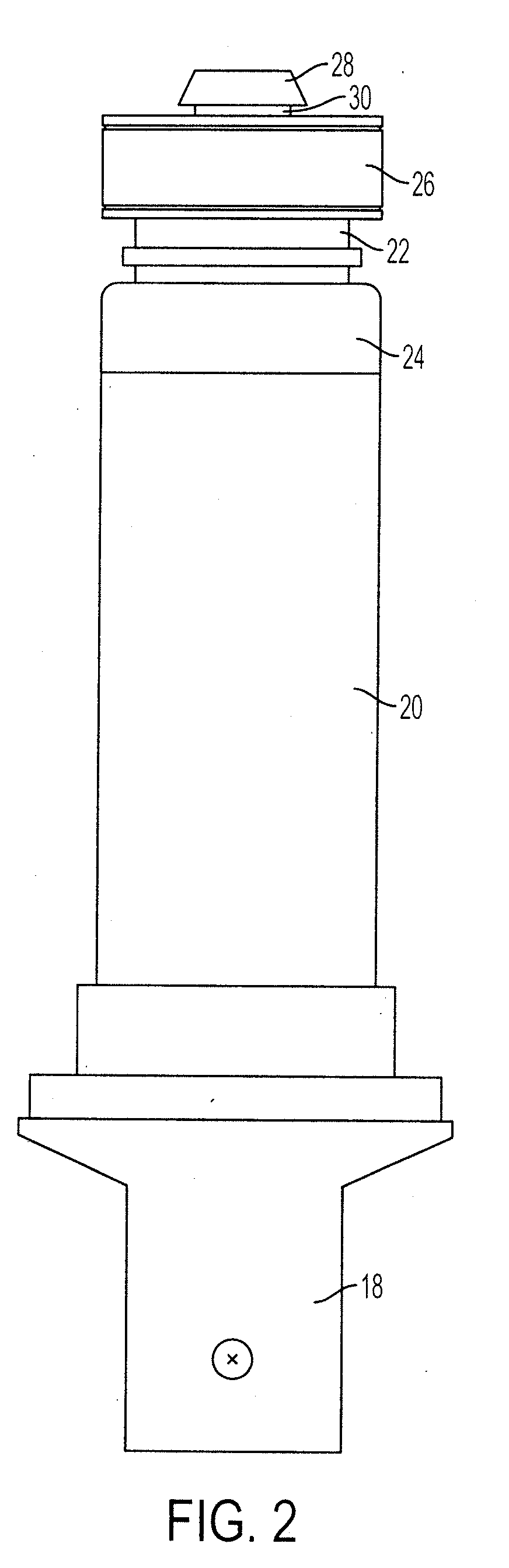
[0014]FIG. 2 illustrates the components of the microphone 10 contained within the tubular shell 12. The microphone 10 includes an inner cylindrical housing 20 having a microphone magnet assembly 22 directly or indirectly seated within its top end. The ...


PUM


Abstract

A microphone includes an annular gap between the inner cylindrical housing and the outer tubular shell such that the undesired acoustical signals entering the microphone from the side and rear flow into and through the annular gap. The signals are ported through a phase reversal entrance circumferentially surrounding a magnet assembly and impact the diaphragm such that the undesired acoustical signals entering the front of the microphone are substantially cancelled out by undesired acoustical signals originating from the side and rear.

Description

FIELD OF THE INVENTION[0001]This invention relates generally to vocal microphones and, in particular, to microphones capable of rejecting undesired background noise.BACKGROUND OF THE INVENTION[0002]Although certain cardioid or unidirectional microphones are designed to pick up sounds emanating primarily from in front of the microphone, it is fairly common that such microphones will also pick up some sounds originating from behind or to the side of the microphone. In order to reduce the amplification of these unwanted sounds, microphones may be designed to purposefully allow these sounds to enter the microphone from the rear or back of the microphone for processing by the dynamic element. Typically there is a time delay between the time the unwanted sounds enter the rear of the microphone and when the sounds enter the front of the microphone. This time delay is beneficial because there is a phase shift in the sound waves entering the front and rear of the microphone. Because of the p...

Claims


Application Information

Patent Timeline
IPC IPC(8): H04R11/04
CPCH04R11/04
Inventor HEIL, ROBERT
Owner HEIL SOUND
Why Eureka
Try Eureka