Luminaire having floating luminous light source

a technology of floating light source and luminaire, which is applied in the field of luminaires, can solve the problems that the lighting designer is limited in his or her ability to readily control the location of the luminous surfa

Inactive Publication Date: 2010-09-02
ABL IP HLDG
View PDF32 Cites 130 Cited by
  • Summary
  • Abstract
  • Description
  • Claims
  • Application Information

AI Technical Summary

Benefits of technology

[0004]The present invention is directed to a luminaire having a planar light waveguide with opposed planar surfaces, which produces a visible and seemingly floating source of light for illuminating a space. The visible source of light appears as one or more discrete luminous areas on the visible planar surface or surfaces of the light waveguide, which is otherwise transparent. Light is fed into the luminaire's transparent light waveguide from an edge or edges of the transparent waveguide by light sources, which are preferably LEDs

Problems solved by technology

However, heretofore, the lighting designer has been limited in his or her ability to readily control the location of the luminous surfaces on architectural lighting fixtures in relati

Method used


Image

  • Luminaire having floating luminous light source
  • Luminaire having floating luminous light source
  • Luminaire having floating luminous light source

Examples


Embodiment Construction

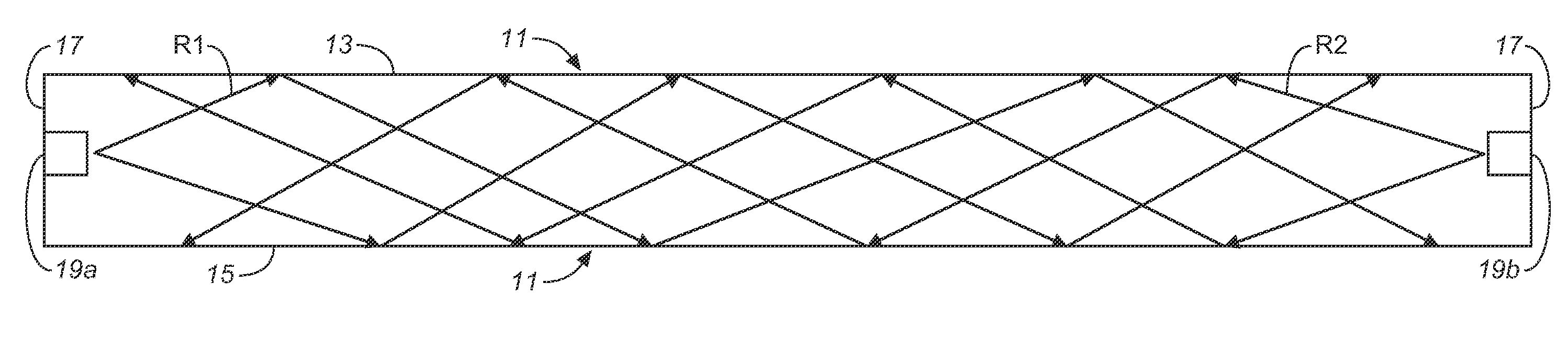
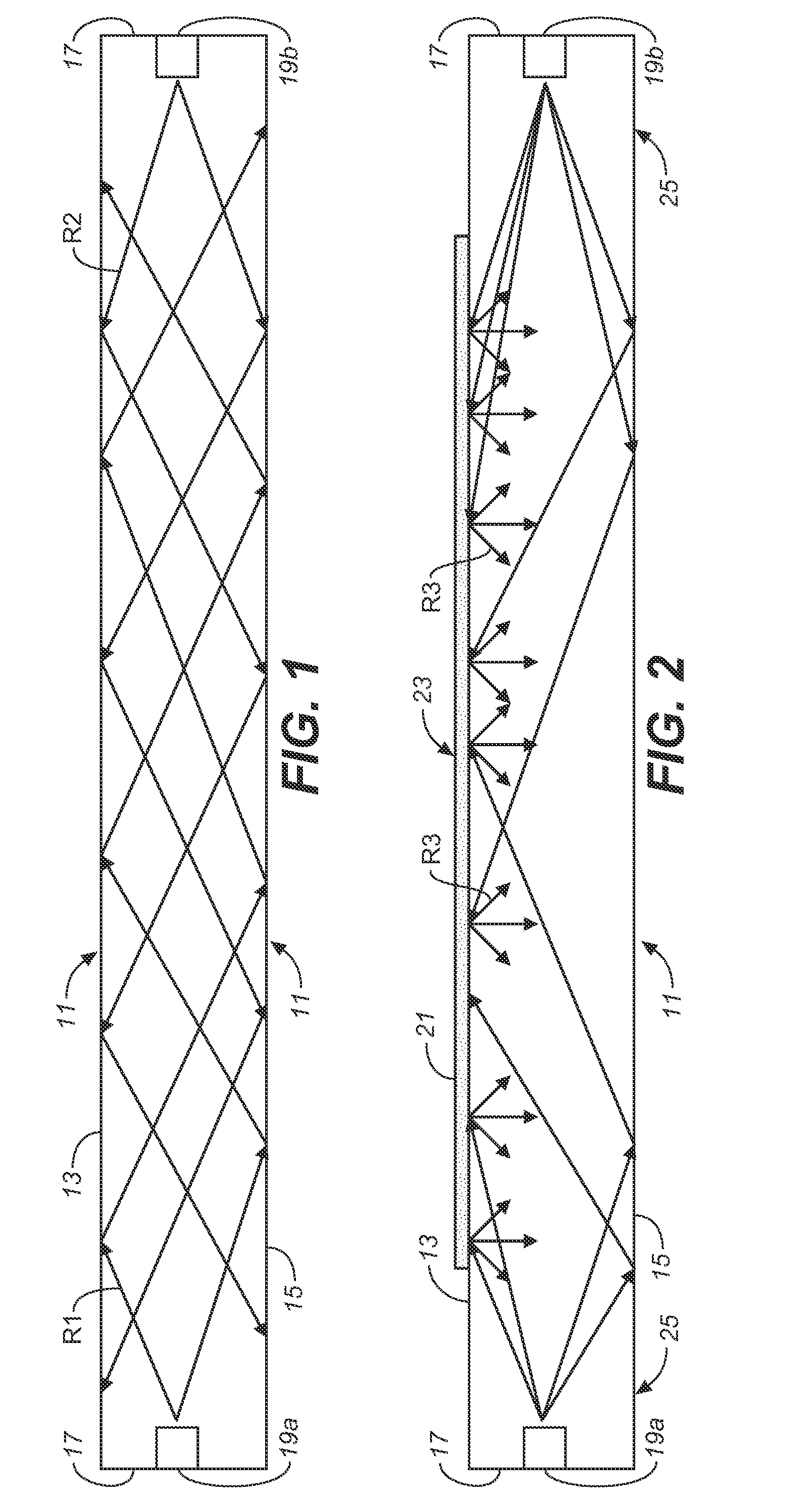
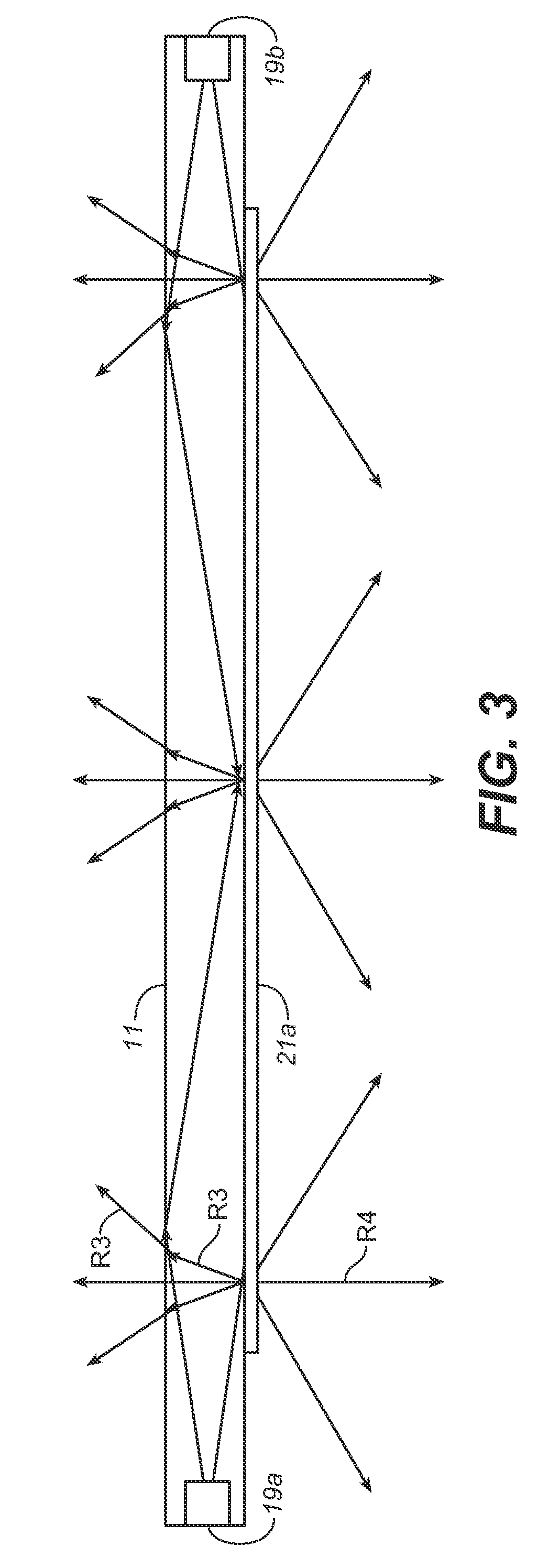
[0021]Light waveguides, also sometimes referred to as “light guides” or “light pipes,” work on the principle of internal reflections governed by Snell's Law. Light introduced at the edges of the guide is internally reflected or “piped” down the guide without emerging from the guide's surfaces, unless and until it is somehow extracted from the guide. This principle is illustrated in FIG. 1, wherein a light waveguide 11, fabricated of a clear, light-transmitting material, has parallel top and bottom surfaces 13, 15 and edges 17 through which light can be introduced into the guide. In the illustrated waveguide, light is introduced into each of the guide's edges 17 by means of light sources 19a, 19b, suitably LEDs, that are shown as being inset into the guide. The light produced by these sources is piped down the guide, as represented by light rays R1 with respect to source 19a, and light rays R2 with respect to source 19b. Because of the low angle of incidence of light rays R1 and R2 o...


PUM


Abstract

A luminaire 31 has a transparent light waveguide 33, which includes a perimeter edge 41, 43, at least one light feed edge portion 41 along its perimeter edge, a visible surface 34, and light extracting means 38. A support structure 49 supports the light waveguide along at least a portion of its perimeter edge, and a light source, such as LEDs 45, is provided for introducing light into the light feed edge portion of the waveguide. Light is extracted from only a portion of the waveguide by the light extracting means. The light extracting means produces one or more luminous areas on a portion of the visible surface of the waveguide, and are positioned on the waveguide such that the luminous area or areas produced thereby give the appearance of a source of light for the luminaire that is substantially detached from the luminaire's support structure.

Description

BACKGROUND OF THE INVENTION[0001]The present invention generally relates to luminaires, and more particularly to luminaires having a source of light that is observable at normal viewing angles within a space. The invention has particular application in architectural lighting, where luminaires contribute to the surrounding architectural environment.[0002]Architectural lighting fixtures having observable sources of light are well known. The observable sources of light are provided by exposed lamps and / or luminous areas on shielding elements or optical elements used for light controls, such as lenses, diffusers and reflectors. Architectural lighting fixtures are integrated into the architectural space using various mounting and suspension schemes, and include recessed lighting and wall-mounted, furniture-mounted, and ceiling-suspended fixtures.[0003]In creating a lighting environment for an architectural space, lighting designers have many tools available to them for designing lighting...

Claims


Application Information

Patent Timeline
IPC IPC(8): F21V7/04
CPCG02B6/002G02B6/0043G02B6/006F21S8/06G02B6/0073G02B6/0085G02B6/0068F21V7/0016
Inventor NGAI, PETER Y.Y.
Owner ABL IP HLDG
Why Eureka
Try Eureka