Polarization mode dispersion compensation

a technology of dispersion compensation and polarization mode, which is applied in the direction of transmission monitoring, transmission monitoring/testing/fault-measurement systems, electrical equipment, etc., can solve the problems of fixed compensation amount, difficult control of launch state, and inability to adjust the dispersion of polarization mode suitable for a practical communication

Inactive Publication Date: 2001-08-07
RPX CLEARINGHOUSE
View PDF2 Cites 351 Cited by
  • Summary
  • Abstract
  • Description
  • Claims
  • Application Information

AI Technical Summary

Problems solved by technology

In practical systems however, it is difficult to control the launch state to always correspond to one of the principal polarisation states so that an optical signal typically comprises the sum of fast and slow mode components.
This technique however has the disadvantage of making available only a fixed amount of compensation and therefore does not allow variable compensation of polarisation mode dispersion suitable for a practical communications system.
A further disadvantage is that a delay element providing optical delay by transmission via a fibre will typically require a relatively long length of fibre in the range 10 to 100 meters.
A disadvantage of this system is that the delay is not continuously and smoothly variable and also requires a relatively complex optical switching configuration.

Method used


Image

  • Polarization mode dispersion compensation
  • Polarization mode dispersion compensation
  • Polarization mode dispersion compensation

Examples


Embodiment Construction

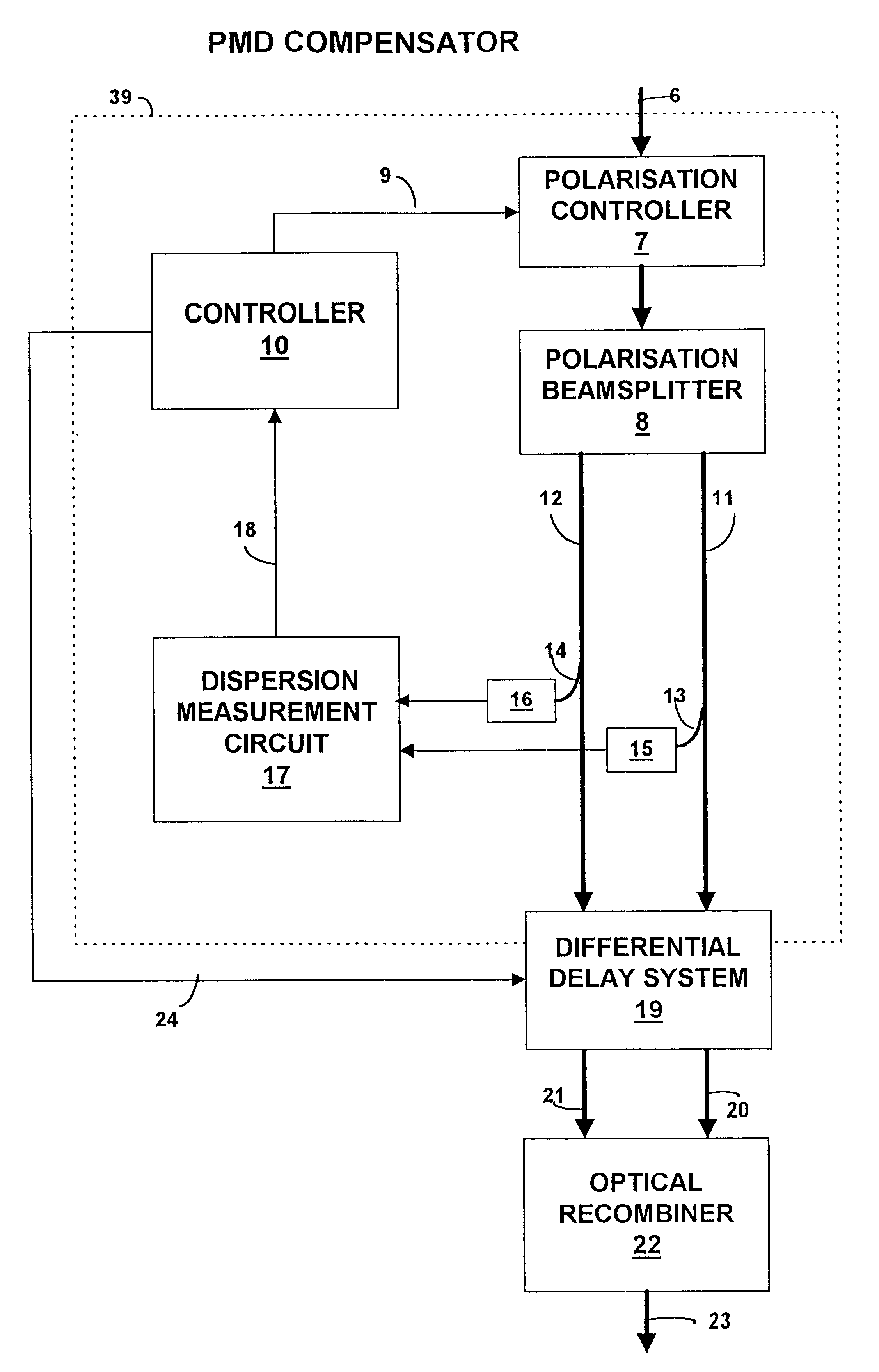
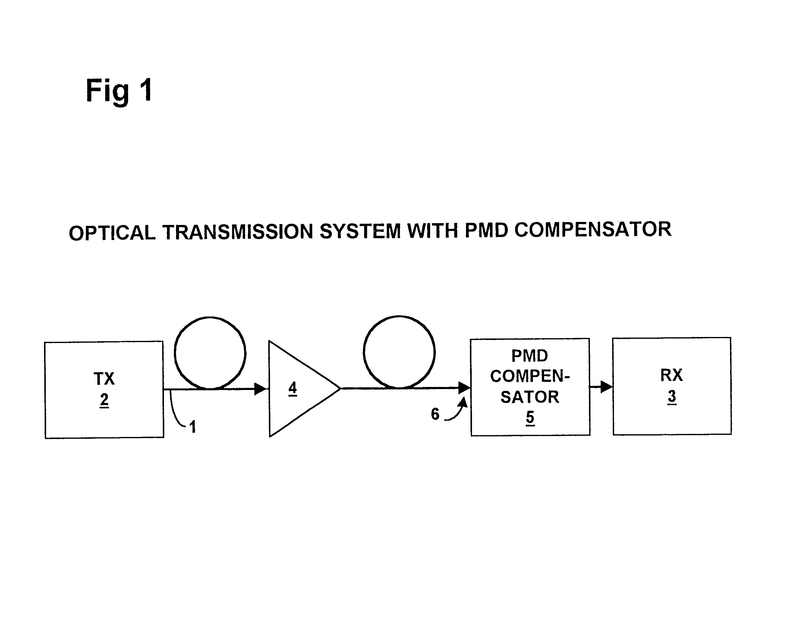
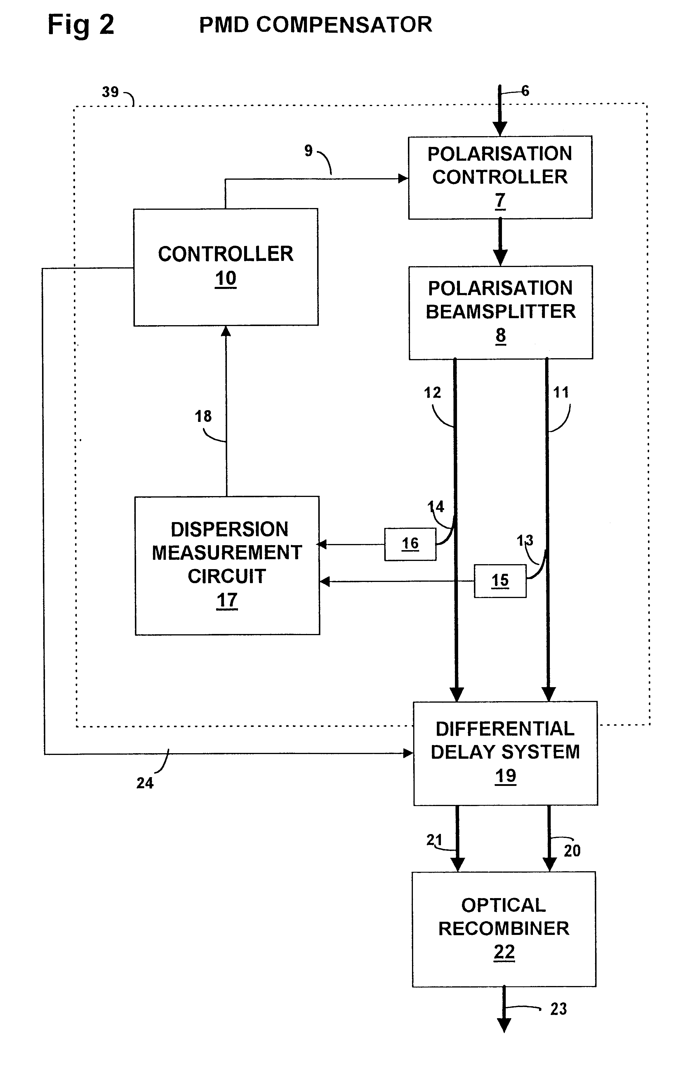
In FIG. 1, an optical fibre 1 provides a transmission path for propagation of an optical signal from a polarised light emitting transmitter 2 to a receiver 3, this transmission path including an erbium doped optical fibre amplifier 4 and, adjacent the receiver 3, a PMD (polarisation mode dispersion) compensator 5.

The optical fibre 1 is a nominally circularly symmetric single mode fibre extending over a substantial distance, which in the present example is 100 km. Over a distance of this length the departures from perfect circular symmetry of that fibre, for example as a result of bending strain, are liable to be of a sufficient magnitude for the fibre to function as a concatenation of birefringent elements of random relative orientation. Moreover that orientation is liable to change with time.

When polarised light of any particular wavelength is transmitted through a single element exhibiting uniform birefringence, that light is, in general, resolved into two components (modes) propa...


PUM


Abstract

Polarization mode dispersion in an optical signal transmitted through a waveguide of a communications system is compensated by separating the dispersed signal into components corresponding to principal polarization states. The components are delayed by respective delays differing by a delay increment which is controlled to correspond to the dispersion delay and the delayed components are recombined to provide a dispersion compensated optical output signal. Each of the delays is provided by an chirped Bragg reflector forming part of a delay line, the Bragg reflectors comprising optical fibres with chirped intracore index gratings. Transducers or temperature controllers acting on one of the fibres allows dimensional control of the grating periodicity such that the position of Bragg reflection is variable. Wavelength division multiplexed optical signals are compensated using sampled gratings which allow a common Bragg reflection position for each wavelength.

Description

This invention relates to compensating for polarisation mode dispersion in an optical signal of an optical communications system and to an optical element for providing a variable differential delay primarily but not exclusively for use in such polarisation mode dispersion compensation.BACKGROUND TO THE INVENTIONExisting communications systems typically rely for transmission over long distances upon the use of nominally single mode optical fibres which carry optical signals and provide transmission of signal data at 10 Gb / sec or more over distances of the order of 100 km. Although such fibres are nominally single mode, propagation of optical signals is generally characterised in such fibres by two orthogonally polarised HE.sub.11 modes for which slightly different group velocities exist in the presence of birefringence.For a given span of optical fibre, the difference in transmission time for these modes is termed polarisation mode dispersion.For the given span of optical fibre, it ...

Claims


Application Information

Patent Timeline
Patent Type & Authority Patents(United States)
IPC IPC(8): H04B10/18
CPCH04B10/2569
Inventor EPWORTH, RICHARD EDWARD
Owner RPX CLEARINGHOUSE
Why Eureka
Try Eureka