[0011]Therefore, it is readily appreciated that there is a need for an improved device and method for MR imaging. It is consequently an object of the invention to provide an MR system and an MR method enabling a safe, reliable and non-interfering transmission of signals and / or power to auxiliary means located within the examination volume.
[0014]In accordance with a preferred embodiment of the invention, the MR system is arranged, for example by a corresponding
programming of the control means and / or the reconstruction means, to acquire a localisation signal generated by the auxiliary means as a response to the second RF signal and to compute the position of the auxiliary means from the localisation signal. A safe active
device tracking technique is realized by this embodiment of the invention. The auxiliary equipment to be localized, which might be, for example, a
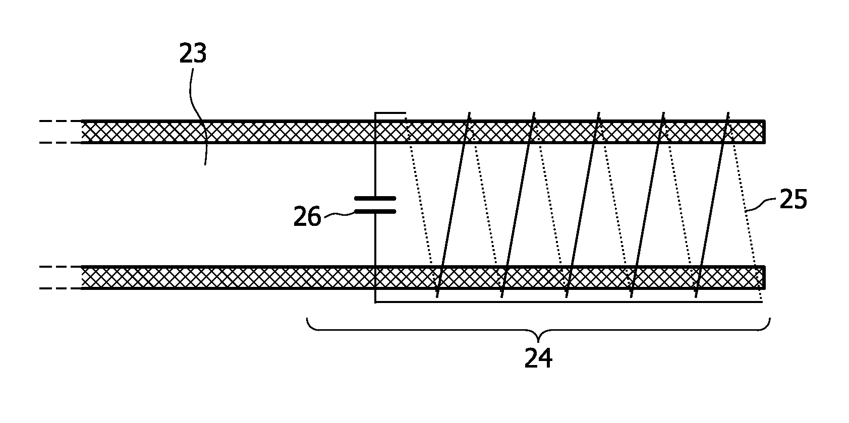
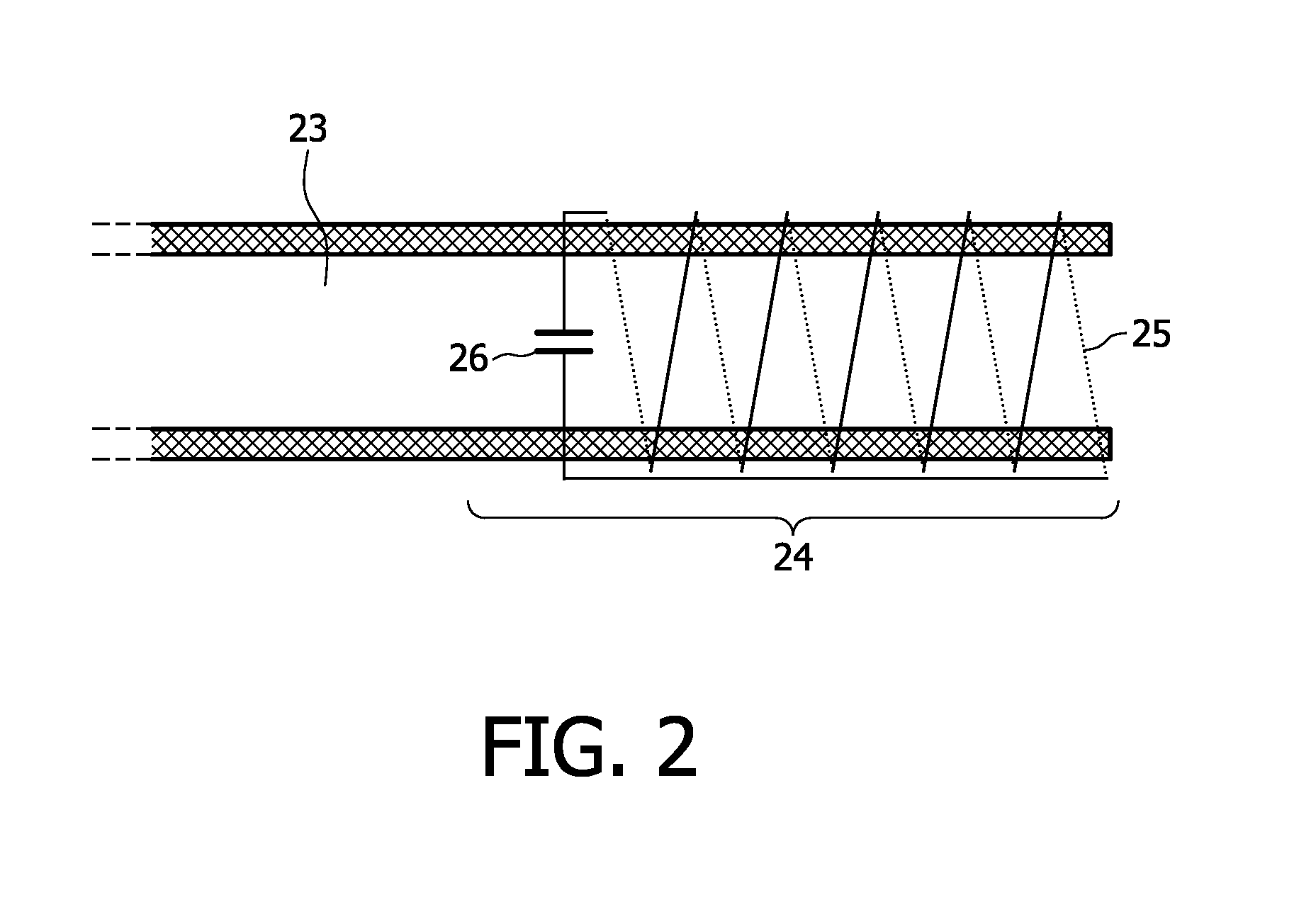
catheter or a guide wire or any other type of interventional instrument, is provided with an RF antenna forming a resonant marker (comprising, for example, a solenoid coil and a
capacitor). For active tracking, RF signals having a reverse polarisation are sent towards the examined body into which the device to be localised is introduced. These RF signals will excite the resonant marker resulting in a strong local B1 field having a linear polarisation. The linearly polarized local B1 field thereupon excites nuclear
magnetization within the
body tissue in the close vicinity of the resonant marker. By a subsequent
data acquisition, MR signals are received only from the direct surroundings of the markers without any background signals from the remainder of the
body tissue. For the purpose of
device tracking, projections in the x-, y-, and z-directions may be simply acquired and reconstructed. Alternatively, a complete MR image can be acquired and reconstructed, which shows image intensity only at the positions of the markers. Such an MR image can be used to compute a color
overlay on a conventionally acquired MR image in order to visualize the positions of the markes in relation to the anatomic features of the examined body. The
device tracking approach of the invention has the
advantage that it can be used with any RF coil for reception including
surface coil arrays. In contrast to the above-described known approach it does not rely on an additional dedicated RF body coil for MR signal reception. A further
advantage is that the technique of the invention provides an improved SNR. This is because the intensity and duration of the reversely polarised RF signals can be chosen to result in a maximum excitation of
magnetization the vicinity of the resonant markers.
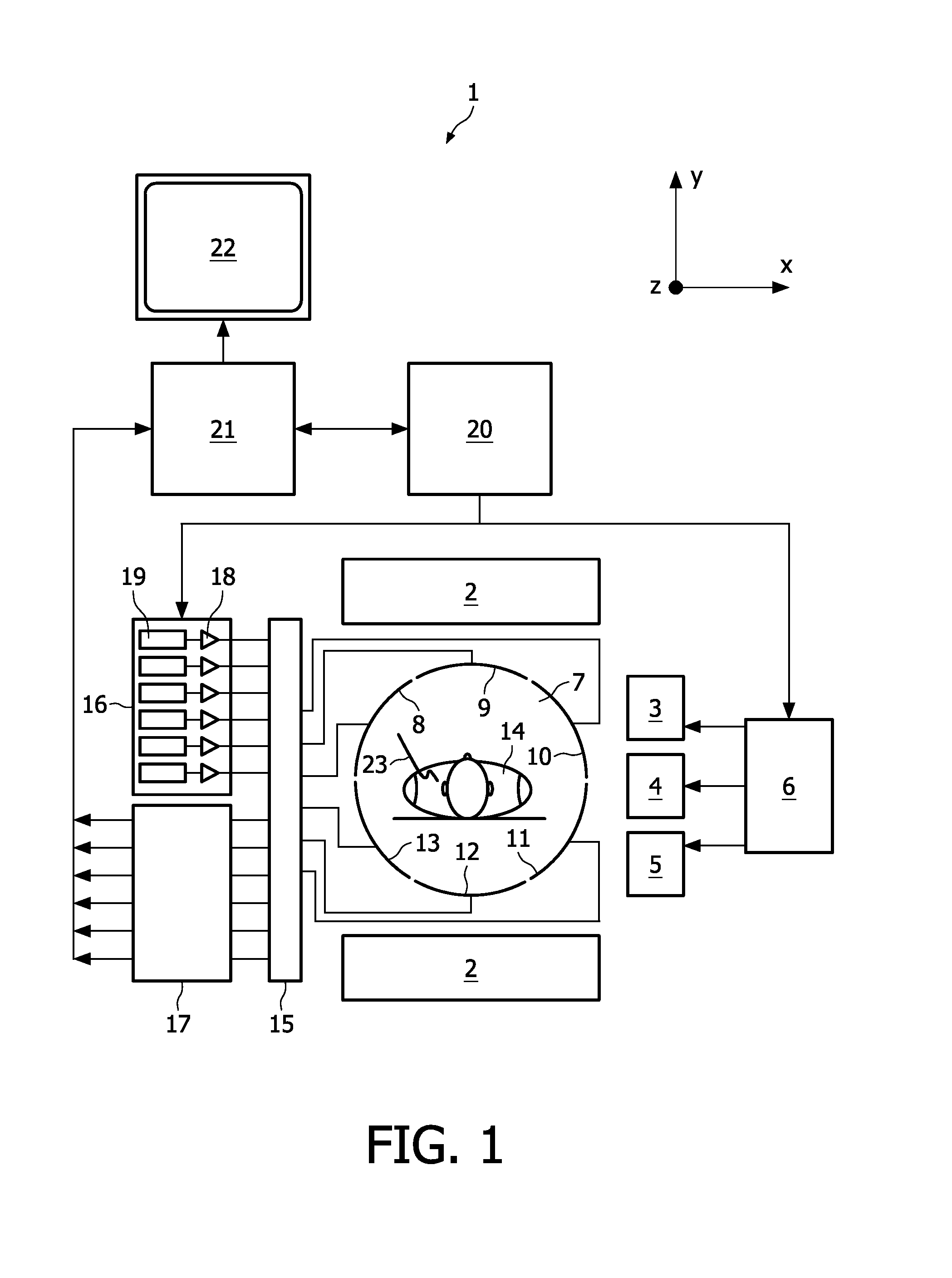
[0017]According to a preferred embodiment of the invention, the transmission means of the MR system comprises a plurality of RF coils forming a multi-
coil array, wherein each RF coil is driven by an individual RF
amplifier and / or an individual RF waveform generator. Recently, MR systems with multi-element RF coil arrays have been introduced for improved MR imaging. Thereby, the multi-element RF
coil array is based on a setup of single RF coils. For example, B1 homogeneity can be controlled during the imaging sequence so as to compensate for varying effects on the field distribution which are due to the different
dielectric properties of the examined body. In order to achieve a selectable B1 distribution within the examination volume, the
single coil elements are driven via separate transmit channels by which the phases and amplitudes of the radiated RF signals can be individually set. The use of such a multi-
coil array for implementing the present invention is straightforward. The generation of reversely polarized RF signals can simply be achieved by prescribing the appropriate waveforms fed to the individual RF coils in the
software of the MR apparatus. Such a system can switch without any
delay between forward and reverse polarisation, and even the simultaneous transmission of both polarisations is possible.

