
Formation testing and evaluation using localized injection

a technology of localized injection and testing and evaluation, which is applied in the direction of reradiation, instruments, and borehole/well accessories, etc., can solve the problems of limiting thereby the amount of hydrocarbon that may be recovered from the formation, or the total production capacity, and drawbacks of ros determination from core analysis, and core analysis may only be representativ

Active Publication Date: 2010-10-21
SCHLUMBERGER TECH CORP
View PDF14 Cites 53 Cited by
  • Summary
  • Abstract
  • Description
  • Claims
  • Application Information

AI Technical Summary

Benefits of technology

The present patent describes methods for evaluating a formation in a wellbore. These methods involve injecting a fluid in the formation and measuring various properties of the formation using a sensor. The sensor can be moved to multiple locations in the wellbore and measurements can be performed at each location. The sensor can also have a larger sensitivity in a specific direction. The methods can be used to determine the formation properties at different locations in the wellbore and at the location where the injection has been successful. The technical effects of the patent are improved methods for evaluating the formation in a wellbore, which can help in the drilling process and production of oil and gas.

Problems solved by technology

Indeed, as the hydrocarbon bearing formation is produced and formation fluid is extracted to a surface location, a portion of the hydrocarbon initially present in the formation pores remains in the formation, limiting thereby the amount of hydrocarbon that may be recovered from the formation, or the total production capacity.
However, there may in some cases be drawbacks to ROS determination from core analysis.
First, core analysis may only be representative of what is happening in the rock matrix at a relatively small scale (e.g. the size of the core), and may not be representative of the formation at a larger scale.
Second, capturing the core(s) may be operationally complex and expensive, and may not be reliable in all formation types, for example in highly fractured formations.
However, as is apparent to the persons skilled in the art, this method involves complex logistics and expensive rig time.

Method used


Image

  • Formation testing and evaluation using localized injection
  • Formation testing and evaluation using localized injection
  • Formation testing and evaluation using localized injection

Examples


Embodiment Construction

[0023]It is to be understood that the following disclosure provides many different embodiments, or examples, for implementing different features of various embodiments. Specific examples of components and arrangements are described below to simplify the present disclosure. These are, of course, merely examples and are not intended to be limiting. In addition, the present disclosure may repeat reference numerals and / or letters in the various examples. This repetition is for the purpose of simplicity and clarity and does not in itself dictate a relationship between the various embodiments and / or configurations discussed. Moreover, the formation of a first feature over or on a second feature in the description that follows may include embodiments in which the first and second features are formed in direct contact, and may also include embodiments in which additional features may be formed interposing the first and second features, such that the first and second features may not be in d...


PUM


Abstract

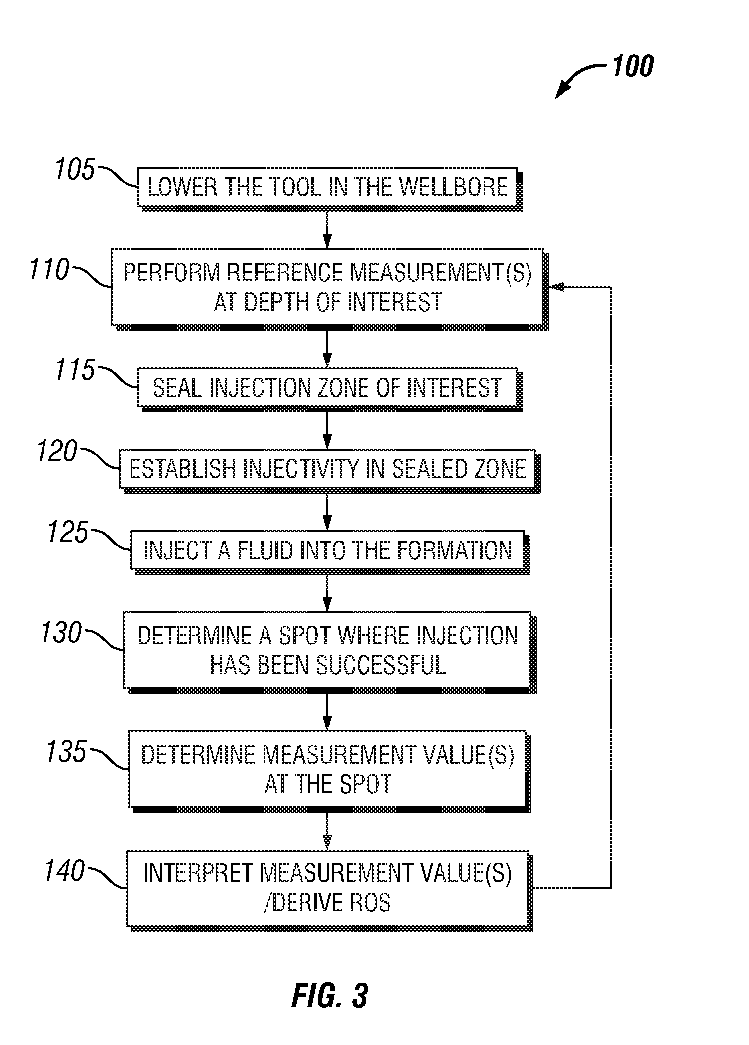
Evaluating a formation by lowering a downhole tool in a wellbore penetrating the formation, injecting a fluid into the formation at an injection zone via the downhole tool, and using a formation evaluation sensor to perform a measurement at each of a plurality of locations in the wellbore each proximate the injection zone. At least two of the plurality of measurements are compared, and a formation property is determined based on the comparison.

Description

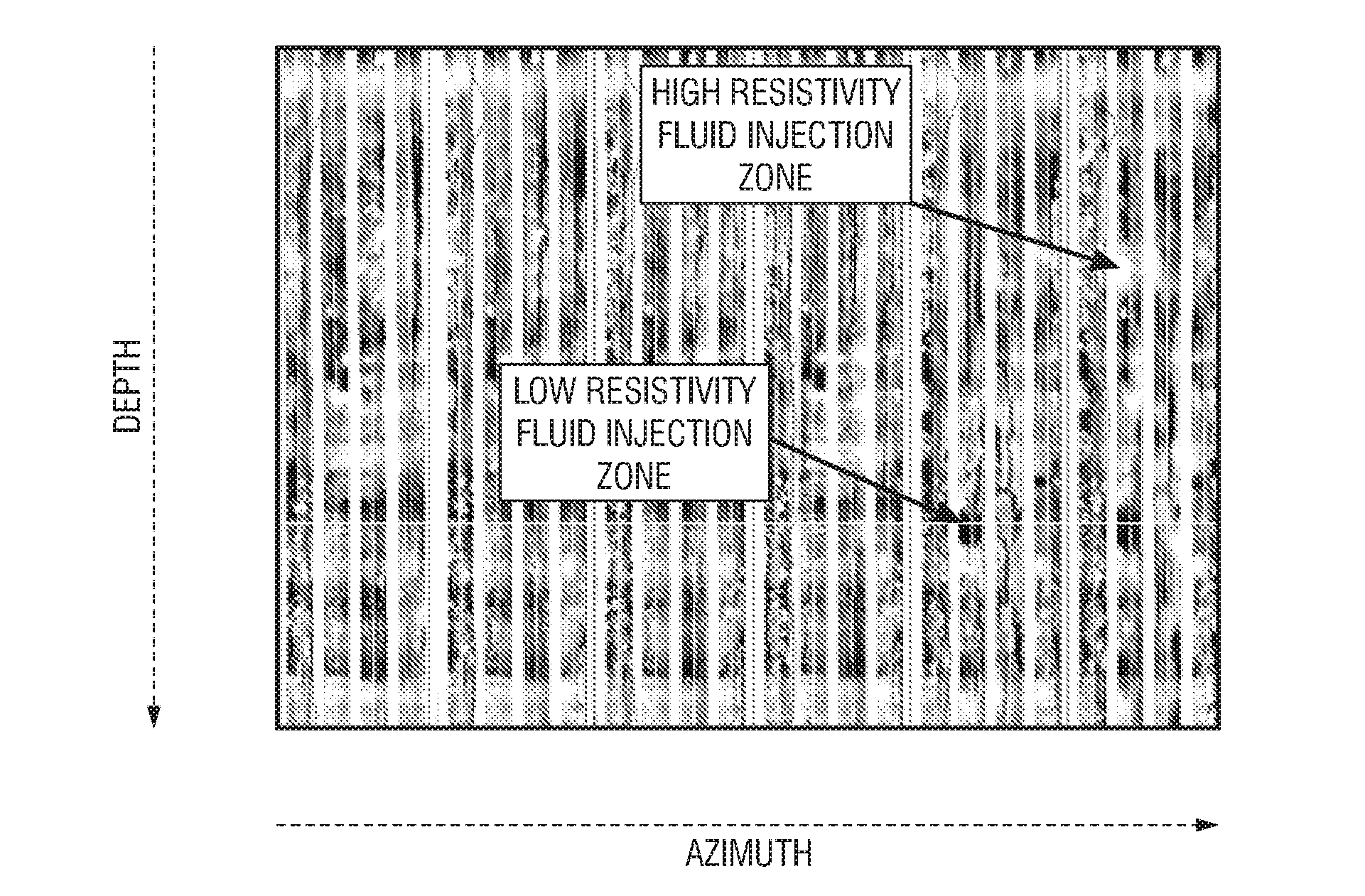
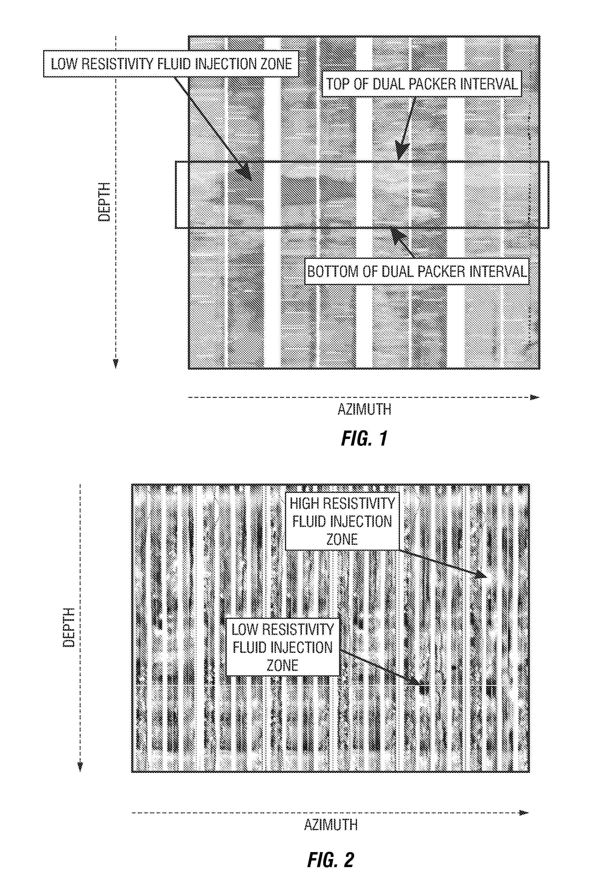
CROSS-REFERENCE TO RELATED APPLICATIONS[0001]This application claims the benefit of U.S. Provisional Application No. 60 / 985,085, entitled “METHOD AND APPARATUS FOR FORMATION TESTING AND EVALUATION,” filed Nov. 2, 2007, Attorney Docket No. 20.3108, the disclosure of which is hereby incorporated herein by reference.[0002]This application also claims the benefit of U.S. Provisional Application No. 61 / 080,364, entitled “METHOD AND APPARATUS FOR FORMATION TESTING AND EVALUATION USING LOCALIZED INJECTION,” filed Jul. 14, 2008, Attorney Docket No. 20.3144, the disclosure of which is hereby incorporated herein by reference.BACKGROUND OF THE DISCLOSURE[0003]Whilst assessing hydrocarbon bearing formations and reservoirs, it is important to acquire knowledge of formation and formation fluid properties which influence the production or yield from the drilled formation. Indeed, as the hydrocarbon bearing formation is produced and formation fluid is extracted to a surface location, a portion of t...

Claims


Application Information

Patent Timeline
Patent Type & Authority Applications(United States)
IPC IPC(8): G01V3/14
CPCE21B43/16G01V3/32E21B49/087
Inventor SALDUNGARAY, PABLOHARRIGAN, EDWARDMONTARON, BARNARDRAMAMOORTHY, RAGHU
Owner SCHLUMBERGER TECH CORP
Learn More