Floatable eyewear

a technology of eyewear and adhesive, which is applied in the field of floating eyewear, can solve the problems of difficulty in manufacturing corrective lenses with an isolated empty chamber, inconvenient or even danger for the wearer trying to retrieve eyewear, and the adhesive loses its function, so as to achieve the effect of being easily found and retrieved by the wearer

a technology of eyewear and adhesive, which is applied in the field of floating eyewear, can solve the problems of difficulty in manufacturing corrective lenses with an isolated empty chamber, inconvenient or even danger for the wearer trying to retrieve eyewear, and the adhesive loses its function, so as to achieve the effect of being easily found and retrieved by the wearer

US20100277685A1Inactive Publication Date: 2010-11-04CHEN CHIH MING

Image

  • Floatable eyewear
  • Floatable eyewear
  • Floatable eyewear

Examples


Embodiment Construction

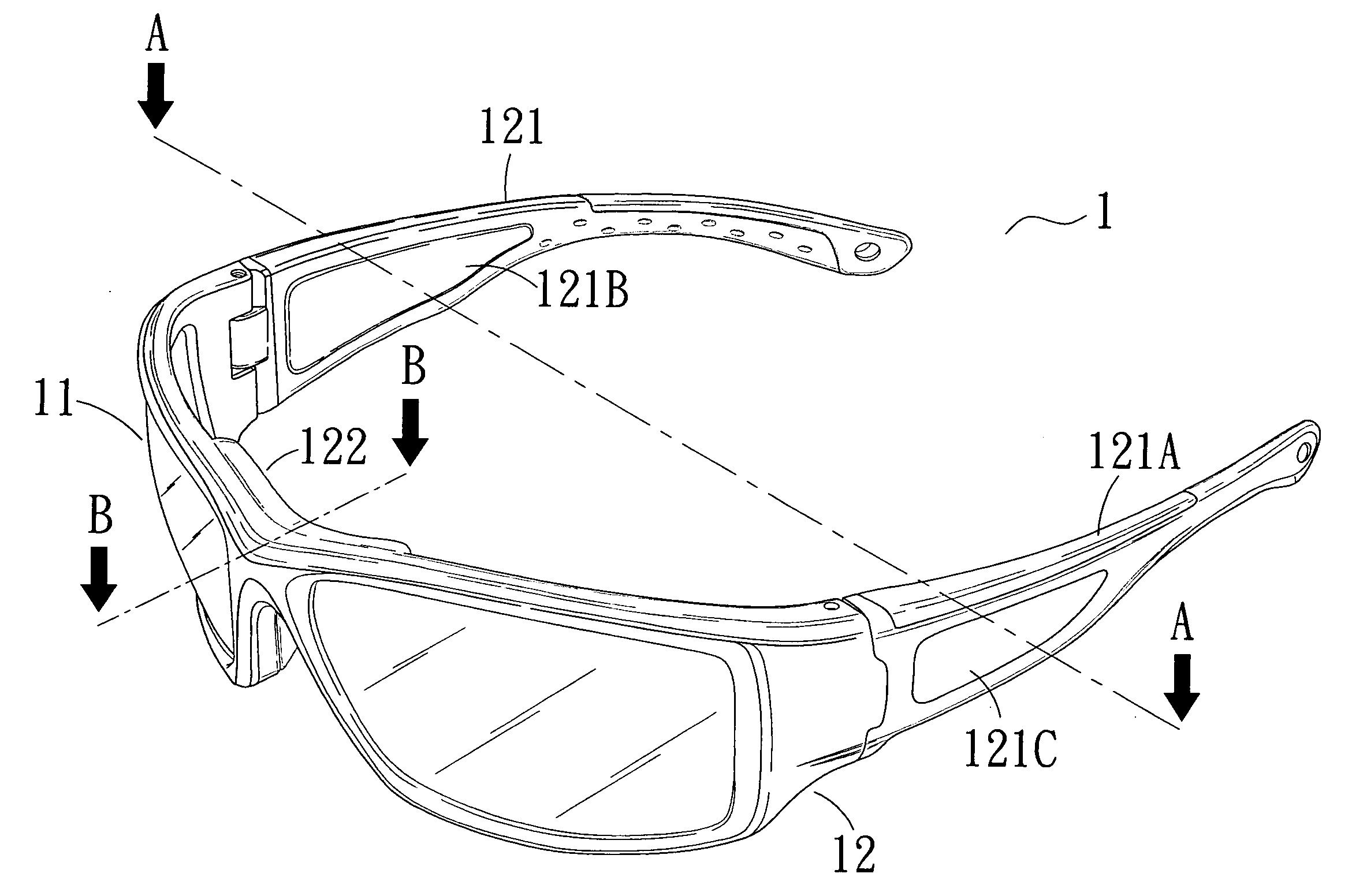
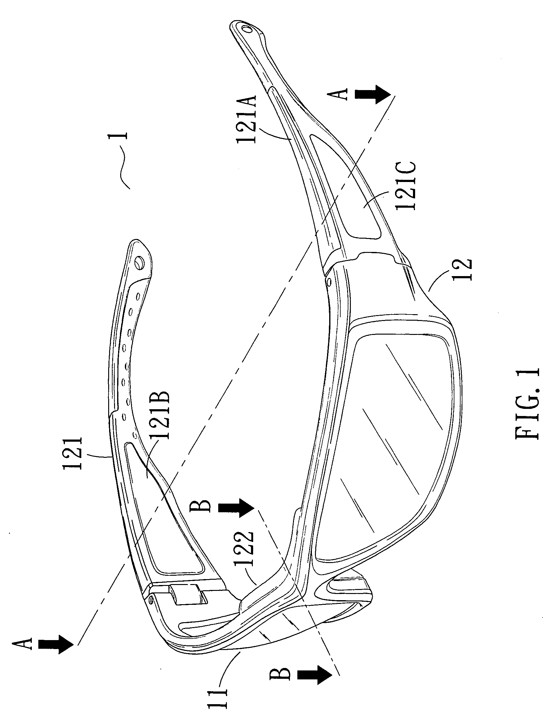
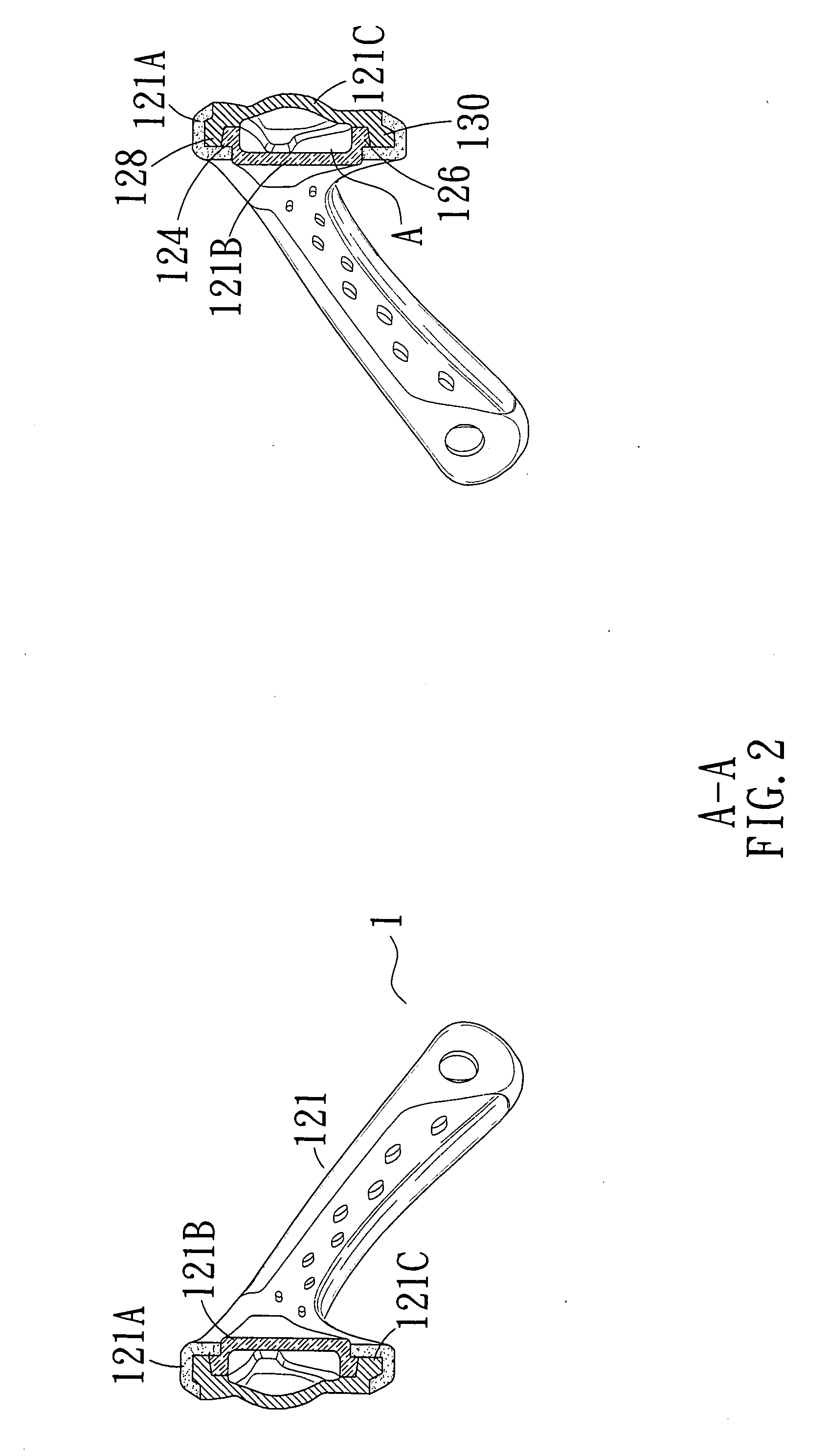
[0013]Floatable eyewear according to the preferred teachings of the present invention is shown in the drawings and generally designated 1. In the preferred form shown, the floatable eyewear 1 includes a lens unit 11 and a frame 12 holding the lens unit 11. In the most preferred form shown, the frame 12 includes a main body 122 and two temples 121 attached to two sides of the main body 122. Each of the main body 122 and the first and second temples 121 includes an empty chamber A, providing the eyewear 1 with buoyancy. The empty chambers A are outside of the lens unit 1.

[0014]Specifically, in the most preferred form shown, each of the first and second temples 121 includes an inner plate 121B and an outer plate 121C. The inner and outer plates 121B and 121C of each temple 121 together define one of the empty chambers A. An upper side 124 of the inner plate 121B is coupled to an upper side 128 of the outer plate 121C. A lower side 126 of the inner plate 121B is coupled to a lower side ...


PUM


Abstract

Floatable eyewear includes a lens unit and a frame holding the lens unit. The frame includes a main body and two temples attached to two sides of the main body. An empty chamber is defined in at least one of the main body and the temples to provide the eyewear with buoyancy. The empty chamber is outside of the lens unit.

Description

BACKGROUND OF THE INVENTION[0001]The present invention relates to floatable eyewear and, more particularly, to eyewear including a floatable frame to provide the eyewear with buoyancy.[0002]People suffering from myopia, hyperopia, and astigmatism need eyewear with correcting lenses to prevent water from entering the eyes while proceeding with activities in, on, or near water, such as fishing, swimming, diving, water volleyball, surfing, water motorcycling, water ballet, etc. However, it is not uncommon that the eyewear falls and, thus, sinks into the water, leading to inconvenience or even danger to the wearer trying to retrieve the eyewear. U.S. Patent Publication No. US20050144707 A1 discloses goggles for water-related activities including a frame and a wearing portion. The frame includes at least one loop portion receiving at least one lens unit. The lens unit includes two lenses and an airtight spacing loop securely sandwiched between the lenses, defining an isolated empty chamb...

Claims


Application Information

Patent Timeline
04 Nov 2010
Publication
US20100277685A1
IPC
G02C11/00
CPC
A61F9/029; A63B33/00; G02C11/00; G02C5/00; A63B2225/605
Inventors
CHEN, CHIH-MING