
Shell designed for securing in a mortar and mortar designed for such a shell

a shell and mortar technology, applied in the direction of breech mechanism, launching weapon, ammunition loading, etc., can solve the problems of reducing the shell cannot be slashed or slid out of the barrel, and the conventional mortar is not particularly suited to mounting on the vehicle, so as to improve the safety of the shell. , the logistic system of the weapon is simplified, and the cost is less. , the effect of fewer components

Active Publication Date: 2010-12-02
BAE SYST BOFORS
View PDF12 Cites 5 Cited by
  • Summary
  • Abstract
  • Description
  • Claims
  • Application Information

AI Technical Summary

Benefits of technology

[0035]The invention proposed above affords several advantages. No additional components are needed for locking a shell in a specific position in a mortar. The locking part constitutes an integral part of the shell. The logistics system of the weapon is simplified, fewer components need to be handled and transported. The ammunition handling system becomes simpler, faster and less expensive. The shell handling when ramming home is simplified, no additional components need to be fitted to the shell or disposed of after firing. The risk of barrel fracture due to loose parts being burnt on inside the barrel is eliminated.
[0036]According to the invention the locking part may also afford advantages with regard to the performance of the shell, in that the deformable part of the locking part, the tubular flange, the end flange or the locking heels are deformed and straightened out directly rearwards. Straightening out directly rearwards is reckoned to have a beneficial effect on the stabilization characteristics of the shell, since the part directed rearwards functions as an additional fin.
[0037]Further advantages and effects will emerge from a study and consideration of the following

Problems solved by technology

Conventional mortars are not especially suited to mounting on vehicles.
A further problem is that the shell lies loosely in the barrel, which means that the mortar can only be fired with a high angle of elevation.
If attempts are made to tip the mortar, that is to say to lower the barrel below a certain angle of elevation, there is a great risk that the shell will shift or slide out of the barrel.
Due to the high pressure and temperature that occur in firing, there is often a risk of the locking element being burned onto or otherwise adhering to the to the breech opening, which in the worst case can lead to fracture of the barrel.
Handling the locking element therefore entails a slower and more complicated weapons system, in which the risk of barrel fracture is great owing to the locking element.

Method used


Image

  • Shell designed for securing in a mortar and mortar designed for such a shell
  • Shell designed for securing in a mortar and mortar designed for such a shell
  • Shell designed for securing in a mortar and mortar designed for such a shell

Examples


Embodiment Construction

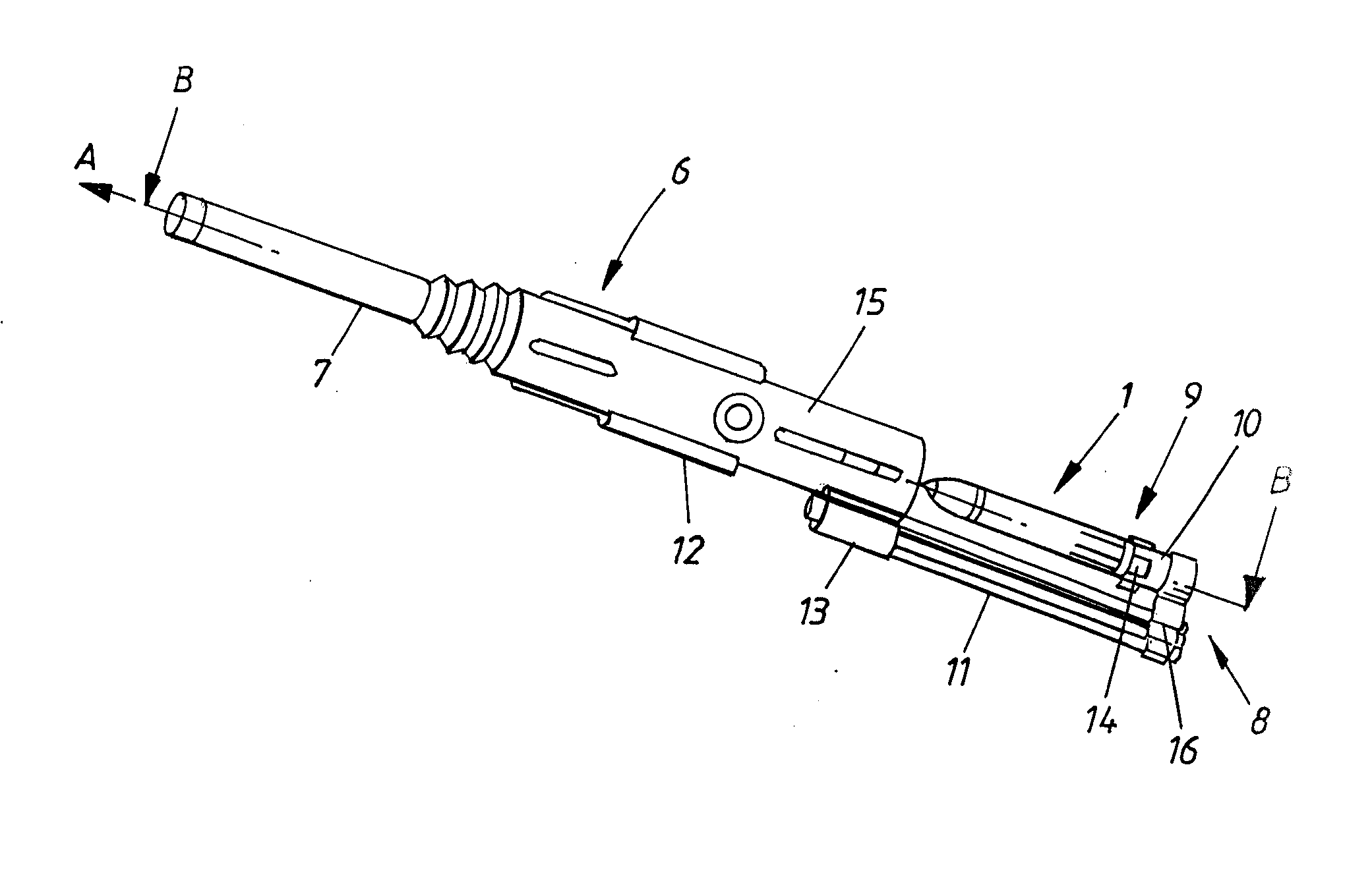
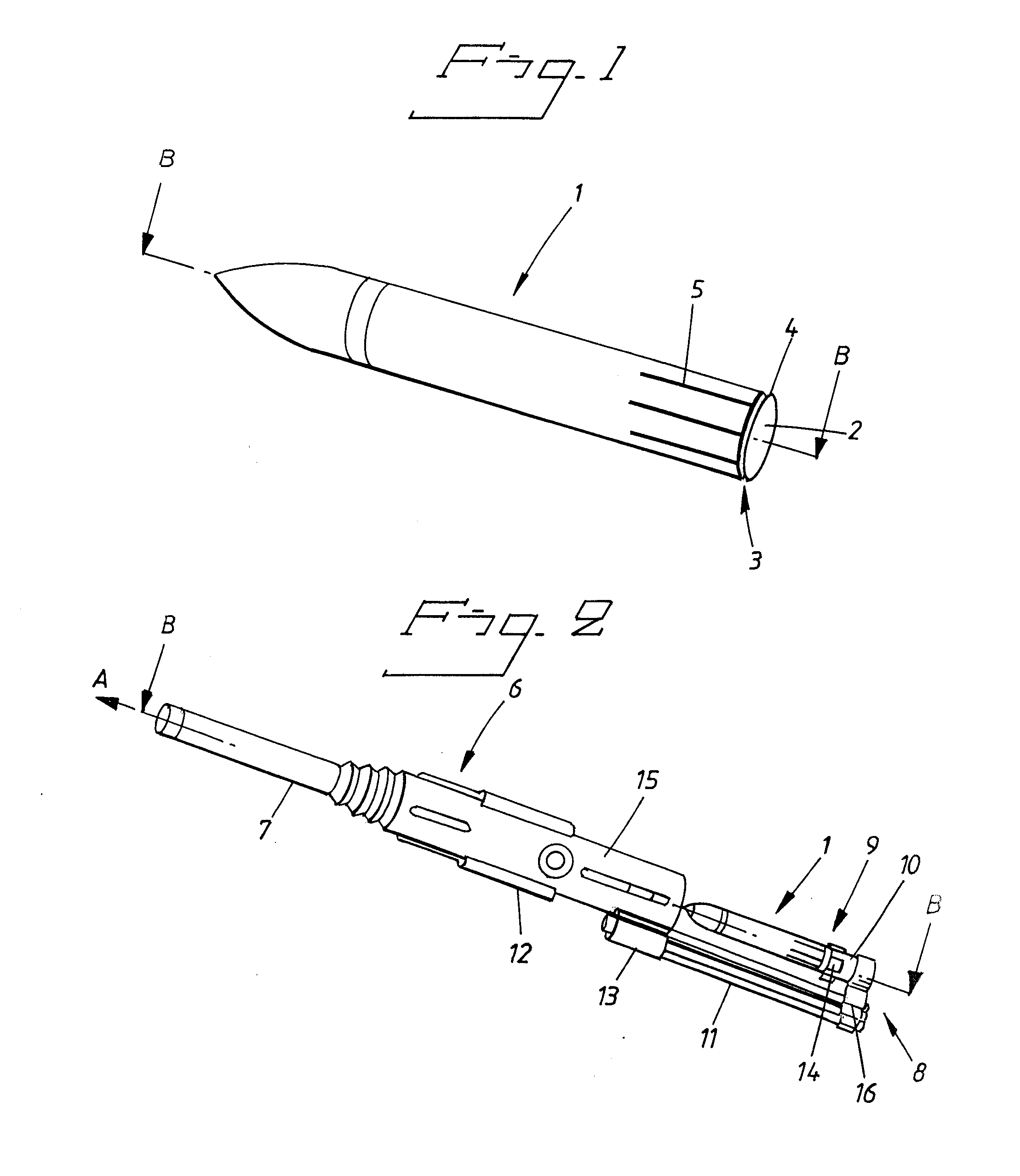
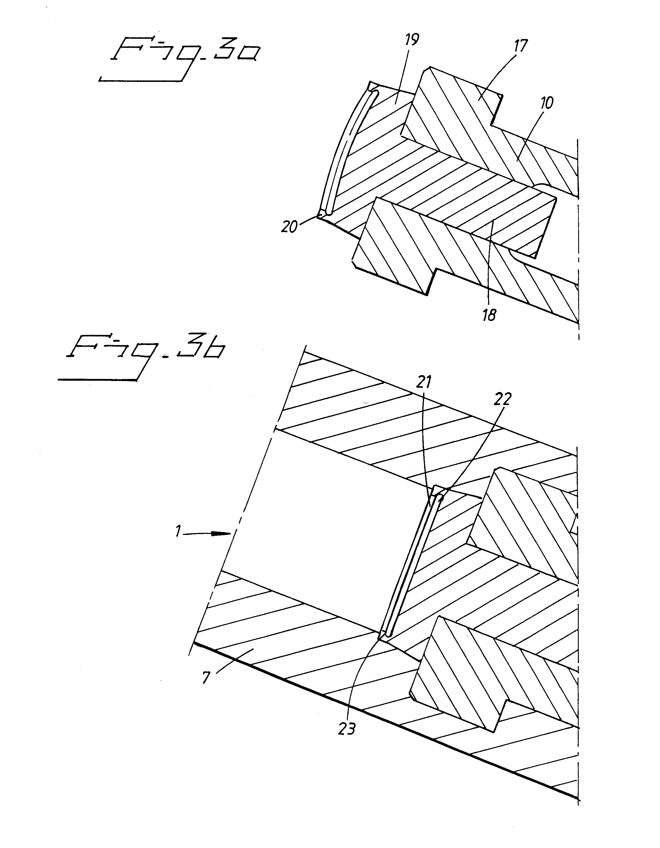
[0041]FIG. 1 shows a preferred embodiment of a shell 1 according to the invention. The shell 1 comprises a locking part 3 arranged at the rear end 2 of the shell 1, the locking part 3 constituting an integral part of the shell 1. The locking part 3 is designed for locking the shell 1 to a corresponding locking part 9, referred to as the securing part 9, arranged in a ramming mechanism of a mortar 6, see FIG. 2. In ramming home the shell 1, the shell 1 is locked in the barrel breech opening of the mortar 6, following which the shell 1 on firing is released by a predefined force acting on the rear end 2 of the shell 1.

[0042]The mortar 6 in FIG. 2 is a motor-driven, automatic breech closure weapon 6, designed for securing the shell 1 according to the embodiment shown in FIG. 1. The mortar 6 is of recoil type and intended for firing shells 1, which can be handled by a mechanical ammunition handling system. The mortar 6 is intended for vehicle-mounting, for mounting on wheeled weapon car...


PUM


Abstract

The invention relates to a shell (1) intended for firing from a weapon (6), preferably a mortar weapon (6), the shell (1) being designed for securing the shell (1) in a mortar weapon (6) in order thereby to prevent movement of the shell (1) when adjusting the angle of elevation of the weapon (6). According to the invention this is achieved in that the shell (1) comprises a locking part (19, 28, 37), the locking part (19, 28, 37) forming an integral part of the shell (1) and being designed so that the shell (1) after ramming home is locked to a corresponding securing part (19) in the mortar (6). The invention also relates to a mortar (6) intended for firing said shell (1), the mortar (6) being characterized in that the mortar (6) comprises a corresponding securing part (19) for locking the shell (1).

Description

[0001]The present invention relates to a shell intended for firing from a weapon, preferably a mortar weapon, the shell being designed for locking in a mortar to prevent movement of the shell when adjusting the angle of elevation of the mortar prior to firing. The invention also relates to a mortar weapon designed for firing said type of shell and a system comprising said shell and mortar.BACKGROUND OF THE INVENTION[0002]Conventional mortar weapons (also referred to as mortars) and mortar ammunition has looked pretty much the same since the days of the First World War.[0003]Conventional mortars are not especially suited to mounting on vehicles. Where installed on vehicles extensive manual handling is required, both of the mortar by redeploying vehicles and of the shell by changing the number of charges. It is necessary either to sacrifice armour protection and to load the mortar manually from open hatches, or to design complicated loading apparatus which moves shells from the inside...

Claims


Application Information

Patent Timeline
Patent Type & Authority Applications(United States)
IPC IPC(8): F42B14/00F41A9/54F41F1/06
CPCF41A3/28F41A3/74F41A9/55F41F3/052F41F1/06F42B30/10F41A9/58F41A9/54F42B14/00
Inventor JOHANSSON, NILS
Owner BAE SYST BOFORS
Learn More