Apparatus and method for controlling input power

a technology of input power and apparatus, applied in the direction of liquid/fluent solid measurement, instruments, high-level techniques, etc., can solve the problems of inconvenience and power wasting, consumption of standby power for minimally driving the devices or systems to recognize user's commands,

Active Publication Date: 2010-12-02
LG ELECTRONICS INC
View PDF4 Cites 52 Cited by
  • Summary
  • Abstract
  • Description
  • Claims
  • Application Information

AI Technical Summary

Benefits of technology

[0017]In one embodiment, there is an apparatus for controlling an input power in a system in which a plurality of power management modes are realized. The apparatus includes: a controller; a user command input in which a user command for setting the power management modes is inputted; a power source (unit) in which a power is supplied according to the respective power management modes set by the user command; and a switch turning OFF all input powers supplied into the power source under the control of the controller when a preset power management mode is set among the plurality of power management modes.
[0018]In another embodiment, there is a method for controlling an input power using a controller, a power source, a user command input, and a switch. The method includes: inputting a user command for setting a power management mode using the user command input; displaying at least two or more power management modes; selecting a saving mode among the power management modes; and controlling the switch under the control of the controller to turn OFF all powers supplied to a system when the saving mode is selected.

Problems solved by technology

However, even during the standby mode, a standby power for minimally driving the devices or systems may be consumed.
Also, when the devices or systems are shifted to a power-OFF status by a user's command, because the devices or systems are powered OFF only to the standby mode, the standby power for minimally driving the devices or systems to recognize user's commands, etc., may be consumed.
This causes inconvenience and power wasting.

Method used


Image

  • Apparatus and method for controlling input power
  • Apparatus and method for controlling input power
  • Apparatus and method for controlling input power

Examples


Embodiment Construction

[0027]Reference will now be made in detail to the embodiments of the present disclosure, examples of which are illustrated in the accompanying drawings.

[0028]First, the terms used herein are selected from terms that are as widely used as possible, but specific terms are arbitrarily selected by the applicant. Since operations and meanings about these specific terms will be described in detail in the detailed description of the invention, the invention should be understood through the operations and meanings of the terms instead of the general terms.

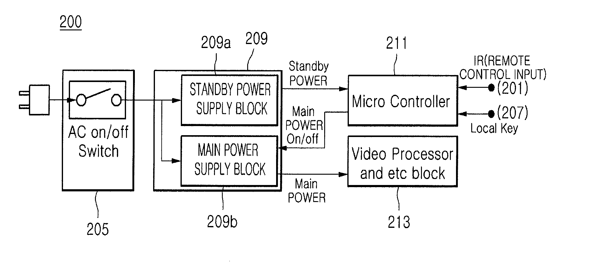
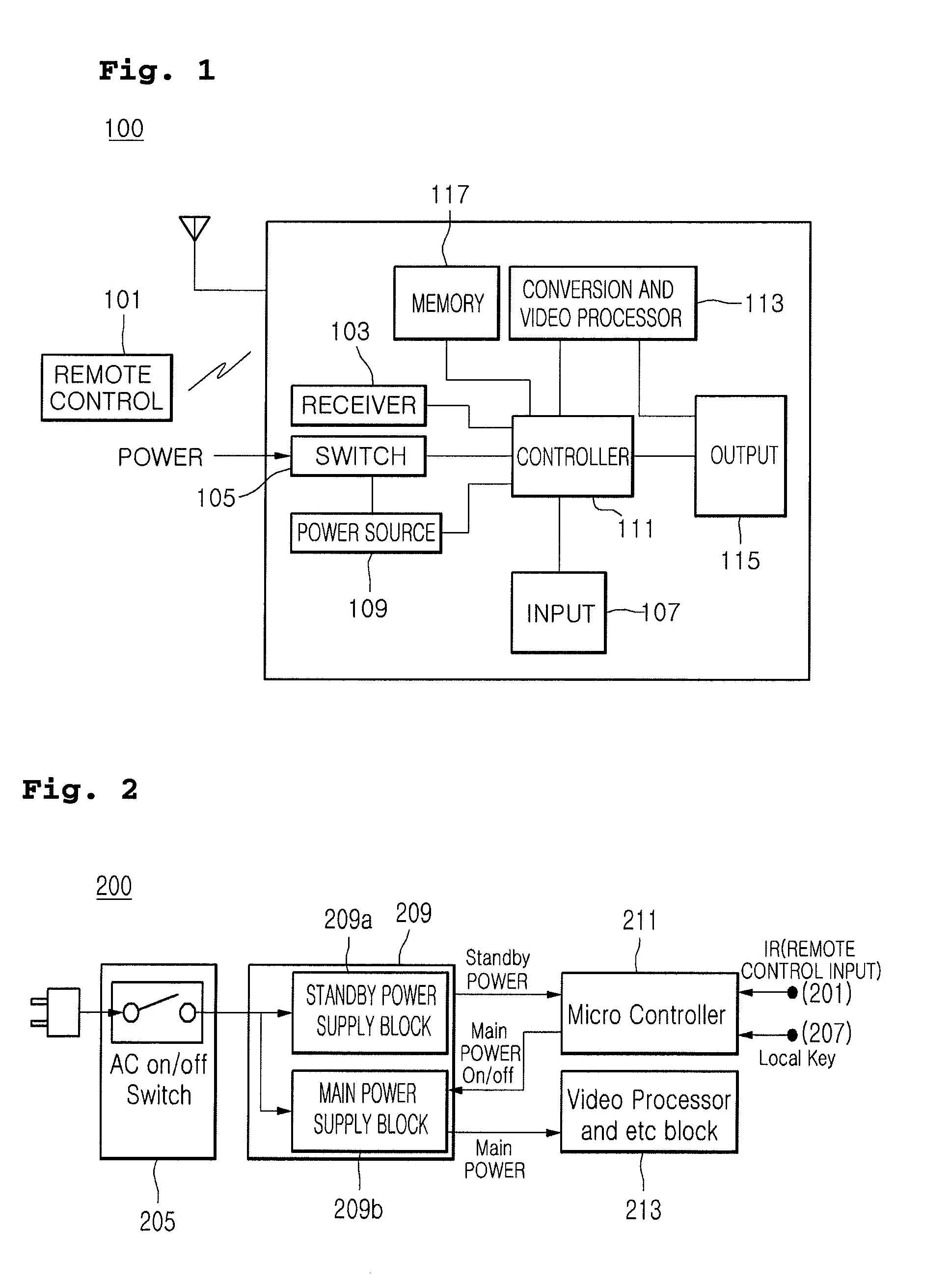
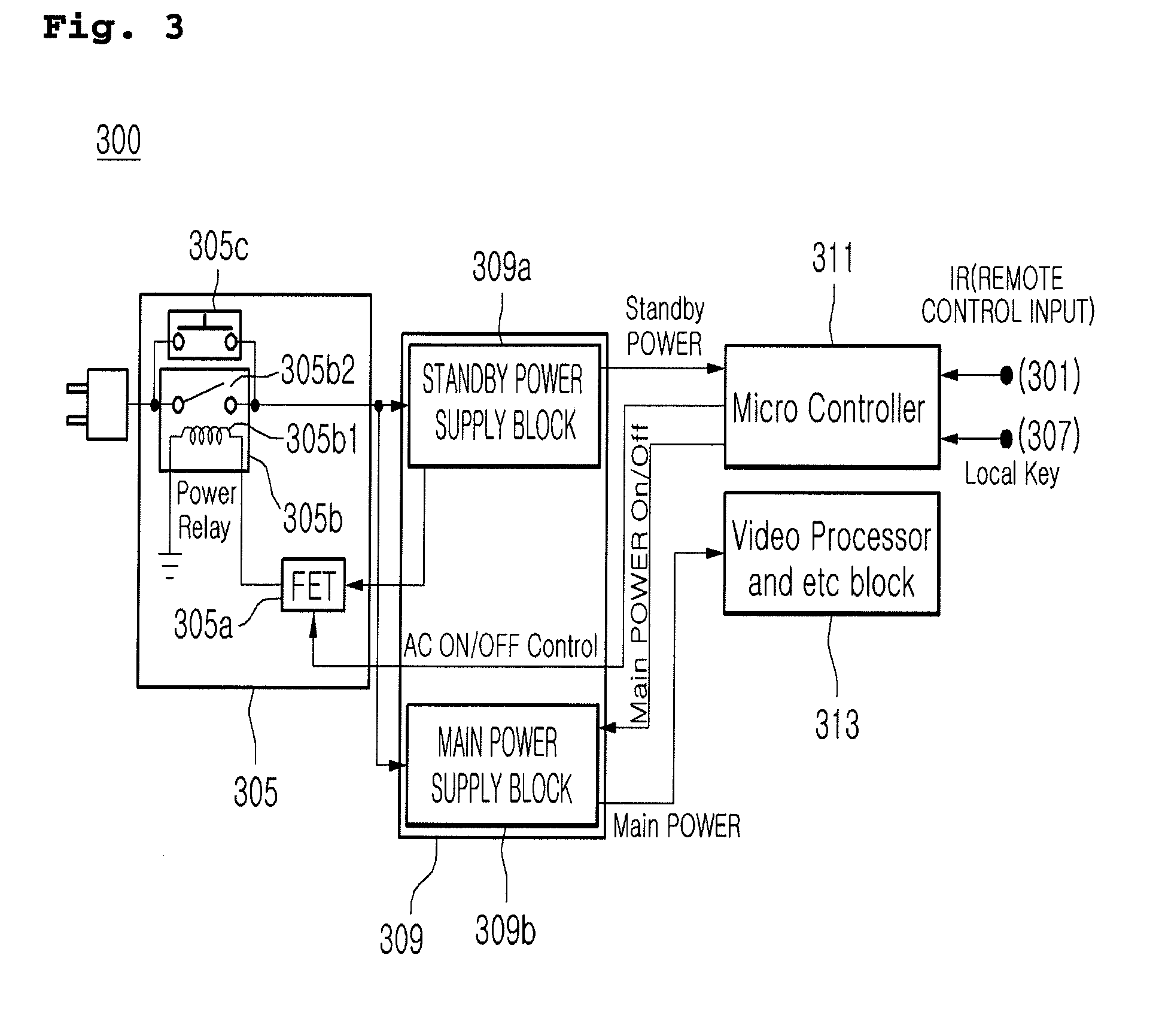
[0029]For example, an OFFAC-OFF status represents a status in which all input powers supplied to a power source (a standby power supply block and a main power supply block) are OFF to realize a zero power consumption state. Thus, the AC-OFF OFFstatus corresponds to a saving mode of the present disclosure.

[0030]A OFFDC-OFF status represents a status in which a power is not supplied to a main power supply block, but supplied to only a standb...


PUM


Abstract

An apparatus and method for controlling an input power according to power management modes of a display device. In a saving mode of the power management modes, a power supply to the system is turned OFF according to an organic operation between components of the system. Thus, because the power supply to a power block within the system is turned OFF all, a consumed power is in a substantially zero state, comparable to a state in which a power plug is physically pulled out.

Description

CROSS-REFERENCE TO RELATED APPLICATIONS[0001]The present application claims priority under 35 U.S.C. 119 and 35 U.S.C. 365 to Korean Patent Application Nos. 10-2009-0048283 (filed on Jun. 1, 2009) and 10-2009-0079103 (filed on Aug. 26, 2009), which are hereby incorporated by references in their entireties.BACKGROUND OF THE INVENTION[0002]1. Field of Invention[0003]The present disclosure relates to an apparatus and method for controlling an input power of a device.[0004]2. Discussion of the Background[0005]With conventional power management modes for devices or systems, the devices or systems are automatically set to a standby mode when signals to be inputted into the devices or systems are not detected within a preset time.[0006]However, even during the standby mode, a standby power for minimally driving the devices or systems may be consumed.[0007]Also, when the devices or systems are shifted to a power-OFF status by a user's command, because the devices or systems are powered OFF ...

Claims


Application Information

Patent Timeline
Patent Type & Authority Applications(United States)
IPC IPC(8): G06F1/26
CPCG06F1/26G06F1/3203Y02D50/20Y02D10/172G06F1/3296Y02D10/00Y02D30/50
Inventor KANG, MIN GOO
Owner LG ELECTRONICS INC
Why Eureka
Try Eureka