Electrical connector for a solar module assembly

a solar module and solar panel technology, applied in the direction of one-pole connection, electrical discharge lamp, coupling device connection, etc., can solve the problems of affecting the automatic mounting of the solar panel connector to the solar panel, the profile height is too large, and the clearance behind the back side of the solar panel may be limited

Active Publication Date: 2010-12-09
TYCO ELECTRONICS LOGISTICS AG (CH)
View PDF18 Cites 30 Cited by
  • Summary
  • Abstract
  • Description
  • Claims
  • Application Information

AI Technical Summary

Benefits of technology

[0007]In one embodiment, an electrical connector includes a rigid body, cable mating bodies disposed within the body, and contacts joined to the cable mating bodies. The body has an upper side and an opposite mounting side that is configured to be mounted to a first solar module. The body frames a window that extends through the body from the upper side to the mounting side. The cable mating bodies are configured to electrically couple the first solar module with cables to communicate electric current generated in the first solar module with one or more of an electrical load and an additional solar module. The contacts extend into the window of the body and are arranged in the window to mate with the module contacts to electrically couple the first solar module with the cable mating bodies. Optionally, the body includes ports that are configured to detachably receive the cables coupled to the at least one additional solar module in order to electrically couple the first solar module with the at least one additional solar module. In one embodiment, the body includes opposite ends interconnecting the upper side with the mounting side, with the ports being disposed in the opposite ends. Alternatively, the body includes a common end that interconnects the upper side with the mounting side. The ports may be disposed in this common end.

Problems solved by technology

With the increasing use of solar modules in tight locations and spaces, the clearance behind the back side of solar modules may be limited.
Some known connectors have a profile height that is too large to permit mounting of the connectors to the solar modules in some relatively tight or small locations.
The cables, however, can interfere with the automated mounting of the connectors to the solar modules.
For example, the dangling cables can interfere with automated pick-and-place systems that pick up and place the connectors to the back sides of solar modules in order to mount the connectors to the solar modules.
Moreover, the contacts of some connectors are not located to allow for automated soldering or welding of the contacts with the module contacts.

Method used


Image

  • Electrical connector for a solar module assembly
  • Electrical connector for a solar module assembly
  • Electrical connector for a solar module assembly

Examples


Embodiment Construction

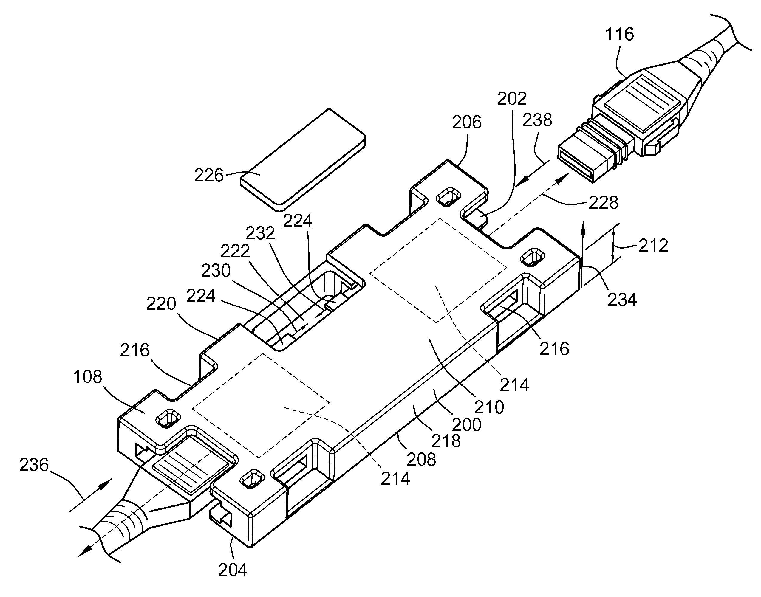
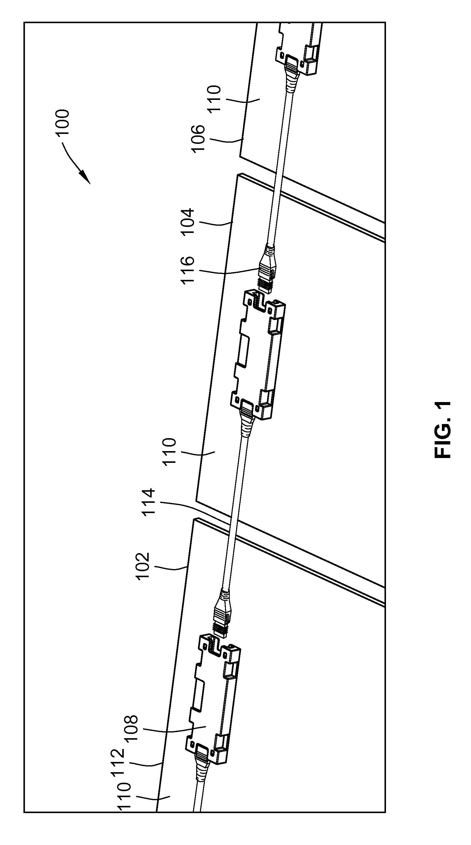
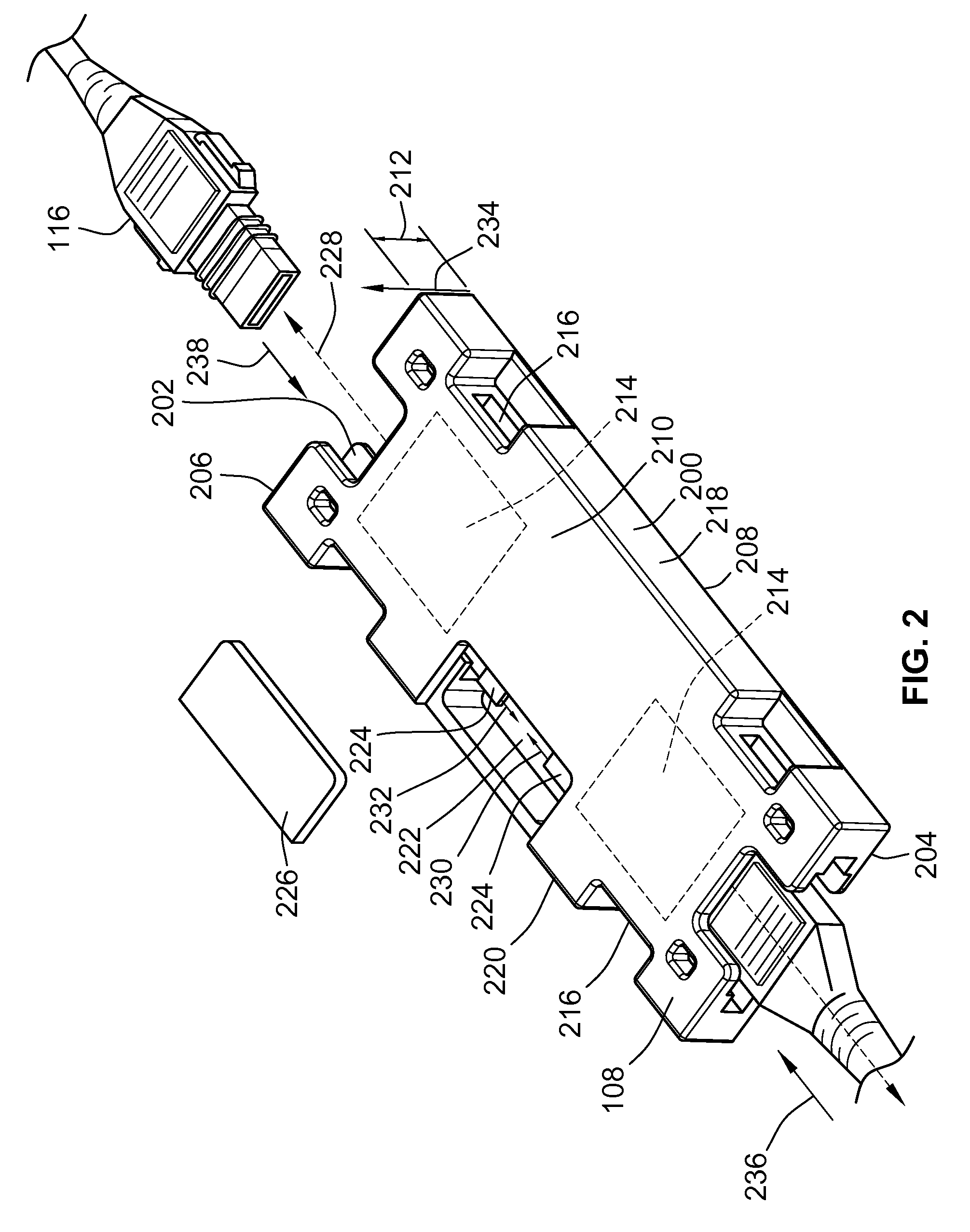
[0018]FIG. 1 is a perspective view of a solar module assembly 100 in accordance with one embodiment of the presently described invention. The solar module assembly 100 includes several solar modules 102, 104, 106. Electrical connectors 108 are electrically joined with and mounted to mounting sides 110 of the solar modules 102, 104, 106. In one embodiment, light that is incident on opposing sides 112 of the solar modules 102-106 is converted into electricity. Alternatively, the connectors 108 may be mounted on the same side 110 or 112 of the solar modules 102, 104, 106 that receives light to convert the light into electricity. The electricity generated by the solar modules 102-106 is communicated to the connectors 108. Several cables 114 interconnect the electrical connectors 108 with one another to permit communication of the generated electricity among the solar modules 102-106. In the embodiment shown in FIG. 1, the cables 114 include plug ends 116. The plug ends 116 are received ...


PUM


Abstract

An electrical connector includes a rigid body, cable mating bodies disposed within the body, and contacts joined to the cable mating bodies. The body has an upper side and an opposite mounting side that is configured to be mounted to a first solar module. The body frames a window that extends through the body from the upper side to the mounting side. The cable mating bodies are configured to electrically couple the first solar module with cables to communicate electric current generated in the first solar module with one or more of an electrical load and an additional solar module. The contacts extend into the window of the body and are arranged in the window to mate with the module contacts to electrically couple the first solar module with the cable mating bodies.

Description

BACKGROUND OF THE INVENTION[0001]The subject matter herein relates generally to electrical connectors and, more particularly, for electrical connectors that couple solar modules with one another.[0002]Solar modules or panels convert incident light into electricity. Known solar modules receive light on one side of the module and convert the light into an electrical potential difference. The electrical potential difference is applied to module contacts positioned at or near an exterior surface of the solar module. An electrical connector is electrically coupled to the module contacts to receive the potential difference. Several electrical connectors mounted to multiple solar modules are joined with one another to combine the electrical potential differences of the solar modules. The potential differences of the solar modules may be combined as an electric current passing through the connectors and modules. The electric current may then be applied to an electric load that uses the curr...

Claims


Application Information

Patent Timeline
Patent Type & Authority Applications(United States)
IPC IPC(8): H01R13/52
CPCH01R13/113H01R13/6273H01R13/6641H02S40/34H01R24/66H01R2101/00H01R24/20H02S40/36Y02E10/50
Inventor COURS, DAVIDSCHLEGEL, SCOTTGHERARDINI, STEPHEN D.
Owner TYCO ELECTRONICS LOGISTICS AG (CH)
Why Eureka
Try Eureka