
Imaging method and device using biometric information for operator authentication

Active Publication Date: 2010-12-16
APPLIED MINDS
View PDF19 Cites 27 Cited by
  • Summary
  • Abstract
  • Description
  • Claims
  • Application Information

AI Technical Summary

Benefits of technology

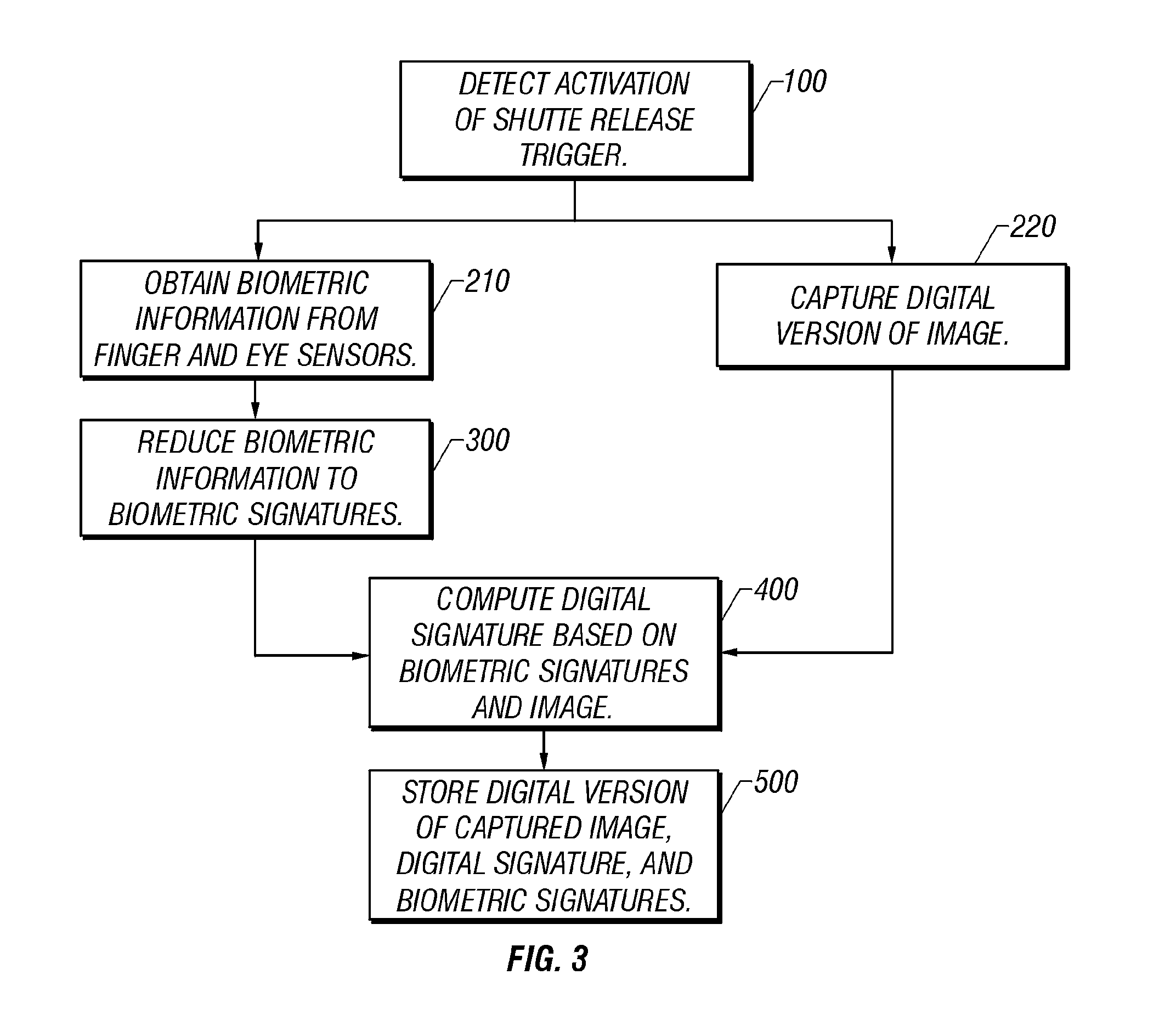
[0024]Prior to storage, the biometric information and captured image may be processed in a manner allowing for subsequent verification that the stored biometric information and stored image have not been altered or falsified. In the presently preferred embodiment of the invention, the imaging device is a digital imaging device, such as a digital camera. In this embodiment, a digital signature is used as the verification mechanism. The digital signature may be computed for the entire captured image and biometric information, or for a message digest computed using a hashing algorithm. Encryption may be applied to the stored image itself to ensure secrecy of the image contents.
[0025]In an alternative embodiment of the invention, the biometric information is acquired before or after the capture of an image by the imaging device, and the imaging device monitors the operator's custody of the imaging device during the intervening period. If the imaging device determines that the operator has maintained custody of the imaging device, the biometric information is stored in association with the image. If the imaging device cannot determine that the operator has maintained custody of the imaging device, it may either forego storage of the biometric information or store the biometric information with an indication that custody of the imagin

Problems solved by technology

However, none of these prior art technologies incorporate or record information in a manner providing reliable identification of the photographer.
Retinal scanners such as theICam 2001™ manufactured by EyeDentify, while more intrusive and typically requiring a more cooperative subject, offer unsurpassed reliability.
However, because there is a potentially substantial delay between the time of operator identification and the time of image capture, this approach provides only limited ability to authenticate the identity of the operator later at the time of image captur

Method used


Image

  • Imaging method and device using biometric information for operator authentication
  • Imaging method and device using biometric information for operator authentication
  • Imaging method and device using biometric information for operator authentication

Examples


Example

[0037]The invention provides an imaging device that stores biometric information in conjunction with a captured image. The biometric information is gathered, processed, and stored in a manner that allows accurate and precise authentication, at a subsequent time, of the operator of the imaging device at the time of image capture, i.e. the photographer who captured the image.

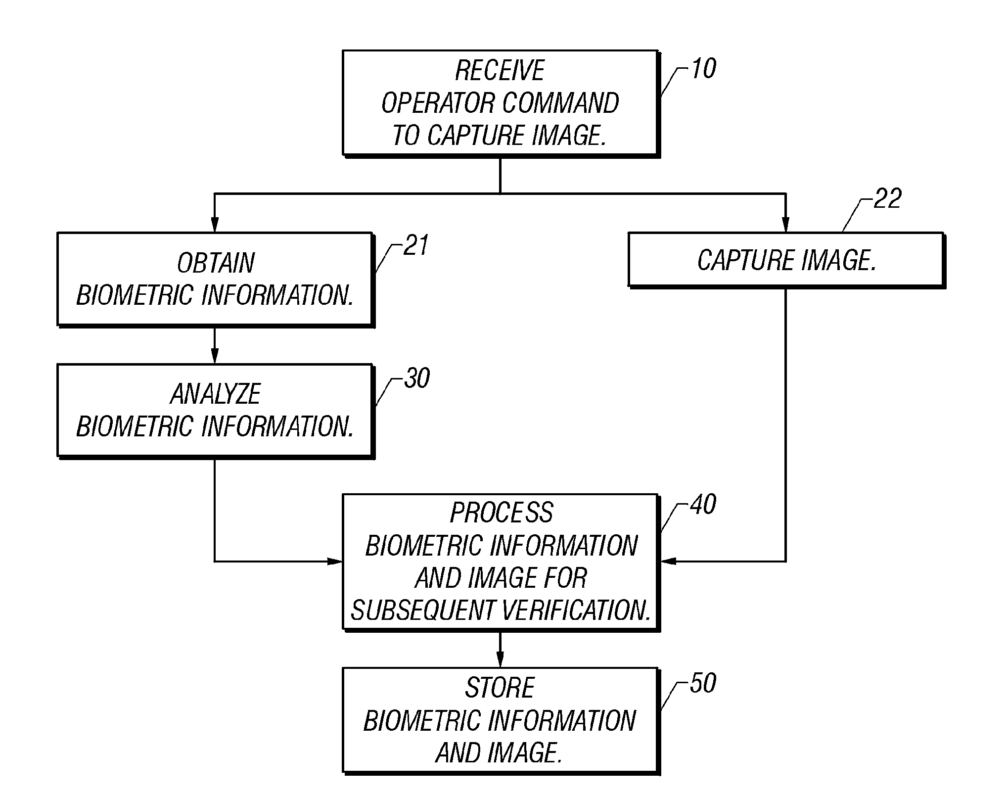
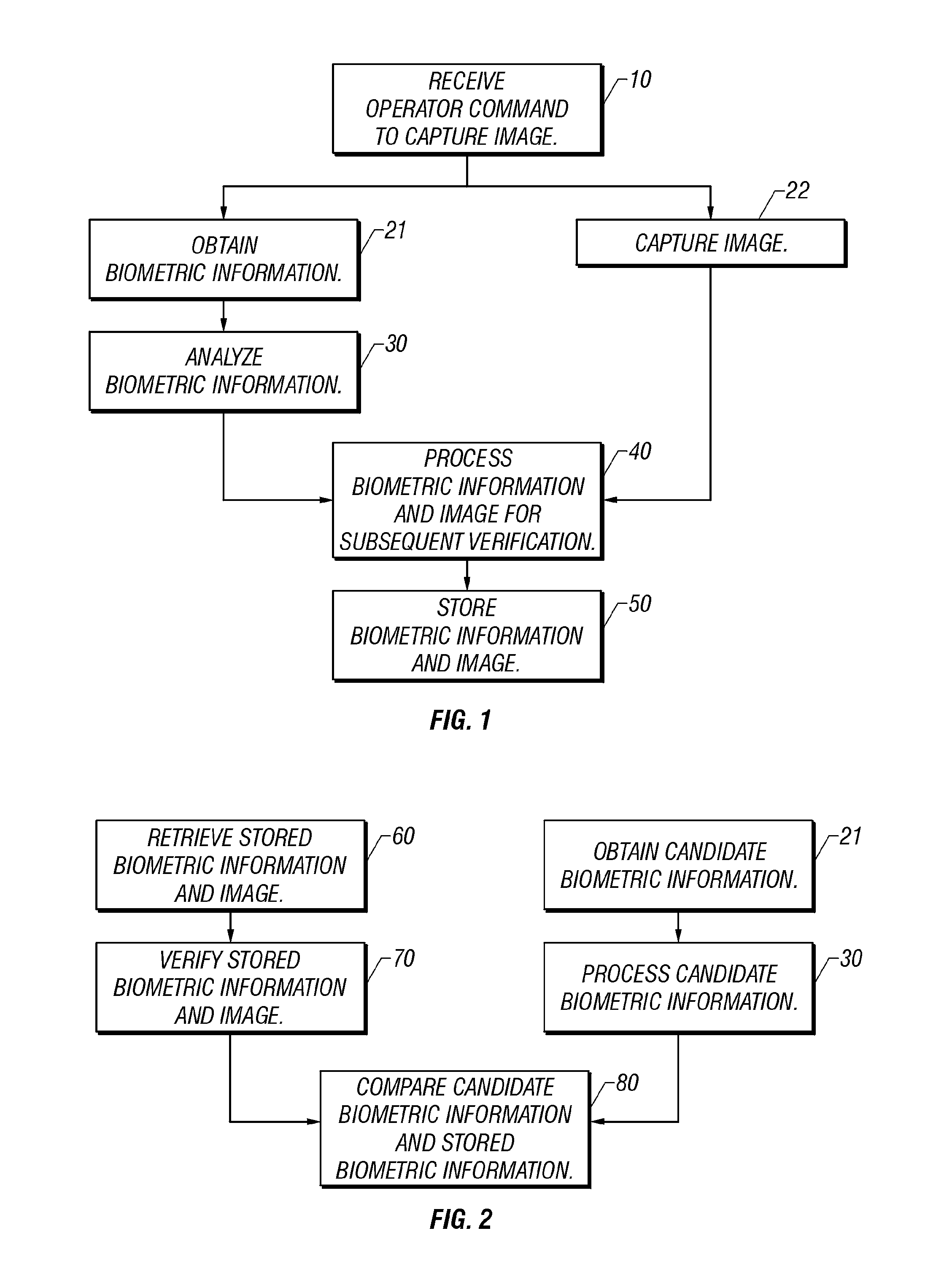
[0038]FIG. 1 shows a sequence of operations, for obtaining and storing biometric information in conjunction with a captured image according to a presently preferred embodiment of the invention. The sequence of operations begins with the receipt 10 of an operator command to capture an image. In response to this command, biometric information describing the operator is obtained 21, and an image is captured 22. In the presently preferred embodiment of the invention, operations 21 and 22 are conducted approximately simultaneously, although the invention is not limited to this sequence and, as discussed in greater deta...


PUM


Abstract

Essentially coincident with the capture of an image by the imaging device, biometric information indicating the identity of the operator of the device is obtained from at least one biometric sensor. The biometric information and captured image are then stored in a manner reliably associating each with the other. At a later time, biometric information is obtained from a supposed operator of the imaging device. By comparing this candidate biometric information with the stored biometric information, the supposed operator may be authenticated as the operator of the imaging device at the time of capture of the stored image.

Description

RELATED APPLICATIONS[0001]This application is a continuation-in-part of U.S. patent application Ser. No. 11 / 352,119, filed Feb. 10, 2006, which is a continuation of U.S. patent application Ser. No. 09 / 995,268, filed Nov. 27, 2001, and which claims priority to U.S. provisional patent application Ser. No. 60 / 250,955, filed Nov. 29, 2000.BACKGROUND[0002]1. Technical Field[0003]This invention relates to the field of imaging devices. More particularly, the invention relates to methods and devices for capturing information for authentication of the imaging device operator.[0004]2. Description of the Prior Art[0005]In many situations, an ability to determine with certainty the details surrounding the creation of a photographic image is of great importance. Information such as the identity of the photographer and the date, time, and location of image creation may all lend credibility to images that are used in legal proceedings, scientific research, and other fields. The advent and wide dis...

Claims


Application Information

Patent Timeline
IPC IPC(8): G06K9/00
CPCG07C9/00158H04N1/2112H04N1/32128H04N1/4406H04N1/442H04N1/444H04N2101/00H04N2201/0084H04N2201/3205H04N2201/3226H04N2201/3233H04N2201/3236H04N2201/3238H04N2201/3239H04N2201/3277H04N2201/3281G06K9/0002H04N5/23219G07C9/37G06V40/1306H04N23/611
Inventor FERREN, BRANHILLIS, W. DANIELHOPE, CLINTON BLAKE
Owner APPLIED MINDS
Learn More