Joint drm am simulcast encoder and transmitter equalizer

a transmitter equalizer and drm am technology, applied in the direction of digital transmission, multi-frequency-changing modulation transference, amplitude demodulation, etc., can solve the problems of increasing the computational complexity of the device and the residual distortion of the resultant output signal, and achieve the effect of simple design

Inactive Publication Date: 2007-09-27
SONY DEUT GMBH
View PDF8 Cites 0 Cited by
  • Summary
  • Abstract
  • Description
  • Claims
  • Application Information

AI Technical Summary

Benefits of technology

[0009]Such an application of a predetermined non-linearity to a signal allows for an estimation of signal degradation / distortion (designated hereinafter simply as “distortion”) that may occur e.g. during amplification and transmission of the signal, i.e. models signal distortion before it occurs, thus allowing it to be compensated. This technique is particularly useful in the context of a simulcast broadcasting system where signal distortion often arises, both in pre-processing steps and during amplification, in the form of undesirable crosstalk and reduced fidelity. Advantageously, the modulated analog signal and / or the modulated digital signal will be any one of the specific such signals described herein.
[0043]The provision of equalization at a stage associated with transmission identical to equalization carried out during signal estimation allows the signal estimation to more realistically simulate the transmission process. Thus, the equalization of any iteration will preferably be identical to the equalization at the transmission stage. In itself, equalization at the transmission stage allows for predistortion of the transmission signal so as to compensate for non-linearities in the amplifier.

Problems solved by technology

The inventors of the present invention have discovered that implementation of the teachings of the aforementioned European patent applications in an encoding device significantly increases the computational complexity of the device.
Moreover, they have discovered that independent solution of the problems posed therein requires high computational power and may result in a larger residual distortion of the resultant output signal as compared to a joint solution.

Method used


Image

  • Joint drm am simulcast encoder and transmitter equalizer
  • Joint drm am simulcast encoder and transmitter equalizer
  • Joint drm am simulcast encoder and transmitter equalizer

Examples


Embodiment Construction

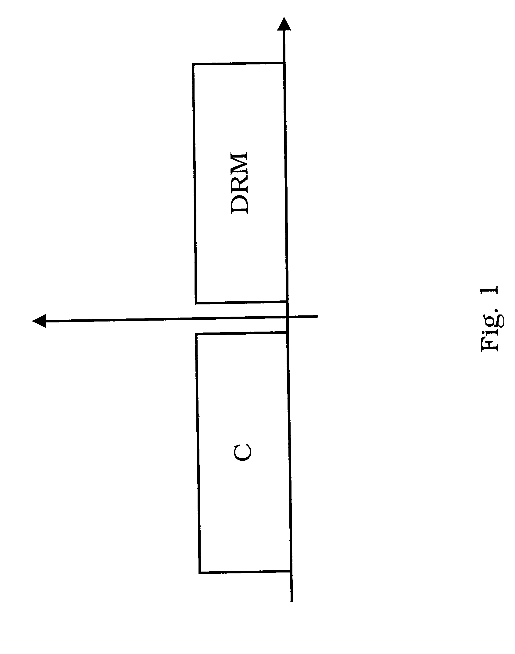
[0050]FIG. 1 schematically illustrates the spectrum of a simulcast signal in accordance with the teachings of EP 1 276 257, i.e. an AM simulcast broadcast signal combining a digital transmission signal and an analog transmission signal into one transmission channel, wherein the digital transmission signal is modulated to one sideband of a carrier of the transmission channel and a correcting signal is modulated to the other sideband of the carrier of the transmission channel, which correcting signal is determined so that the envelope demodulation of the transmission channel represents the analog transmission signal. In DRM (Digital Radio Mondeal) broadcasting, a digital and an analog signal have to be combined in one channel. To avoid distortions of the digital system, the EP 1 276 257 suggests transmitting a digitally modulated signal in one sideband of the channel. This allows distortion-free demodulation of the digitally modulated signal in the receiver. As stated above, the prese...


PUM


Abstract

The present invention relates to a signal estimation apparatus, a signal deviation estimation apparatus, a signal pre-transmission preparation apparatus and a simulcast broadcasting system as well as corresponding methods and a corresponding computer program product. In particular, the present invention relates to the above, wherein a predetermined non-linearity, e.g. for modelling a transmission of a broadcast signal, is applied to a signal so as to obtain an estimation signal e.g. of a transmitted broadcast signal.

Description

BACKGROUND OF THE INVENTION[0001]1. Field of the Invention[0002]The present invention relates to a signal estimation apparatus, a signal deviation estimation apparatus, a signal pre-transmission preparation apparatus and a simulcast broadcasting system as well as corresponding methods and a corresponding computer program product. In particular, the present invention relates to the above, wherein a predetermined non-linearity, e.g. for modelling a transmission of a broadcast signal, is applied to a signal so as to obtain an estimation signal e.g. of a transmitted broadcast signal.[0003]2. Description of the Related Prior Art[0004]European patent application EP 1 276 257 A1, the contents of which are incorporated herein by reference, discloses an AM simulcast broadcast signal that combines a digital transmission signal and an analog transmission signal in one transmission channel.[0005]The inventors of the present invention have discovered that implementation of the teachings of the a...

Claims


Application Information

Patent Timeline
Patent Type & Authority Applications(United States)
IPC IPC(8): H04L27/06H04B1/10
CPCH03D7/16H03C1/60
Inventor WILDHAGEN, JENSSCHILL, DIETMAR
Owner SONY DEUT GMBH
Why Eureka
Try Eureka