System and method of displacing fluids in an annulus

a technology of fluid displacement and annulus, which is applied in the direction of drilling casings, drilling pipes, borehole/well accessories, etc., can solve the problems of internal casing collapse or external casing burst, useless and/or inconvenient retrieval, and oil or gas wells can encounter problems

Active Publication Date: 2010-12-23
VETCO GRAY
View PDF9 Cites 30 Cited by
  • Summary
  • Abstract
  • Description
  • Claims
  • Application Information

AI Technical Summary

Benefits of technology

[0010]Yet another technique is provided for inserting a hose into a pressurized casing annulus and inject fluids without having to relieve the annulus pressure.

Problems solved by technology

When hoses are inserted they are cut or crimped by the sharp corners at the annulus opening (intersection) and are rendered useless and / or can not be retrieved because they will be severed by the sharp corners.
Oil or gas wells can encounter problems with the formation of hydrates (a form of ice) in the casing annulus.
The casing annulus is a confined space therefore the expansion pressure encountered during the formation of hydrates can cause the internal casing to collapse or the external casing to burst.
Both forms of damage are difficult and costly to repair.
Oil or gas wells can encounter problems when the casing develops a hole or the cement job becomes porous and unwanted fluids begin to infiltrate and pressurize the casing annulus.

Method used


Image

  • System and method of displacing fluids in an annulus
  • System and method of displacing fluids in an annulus
  • System and method of displacing fluids in an annulus

Examples


Embodiment Construction

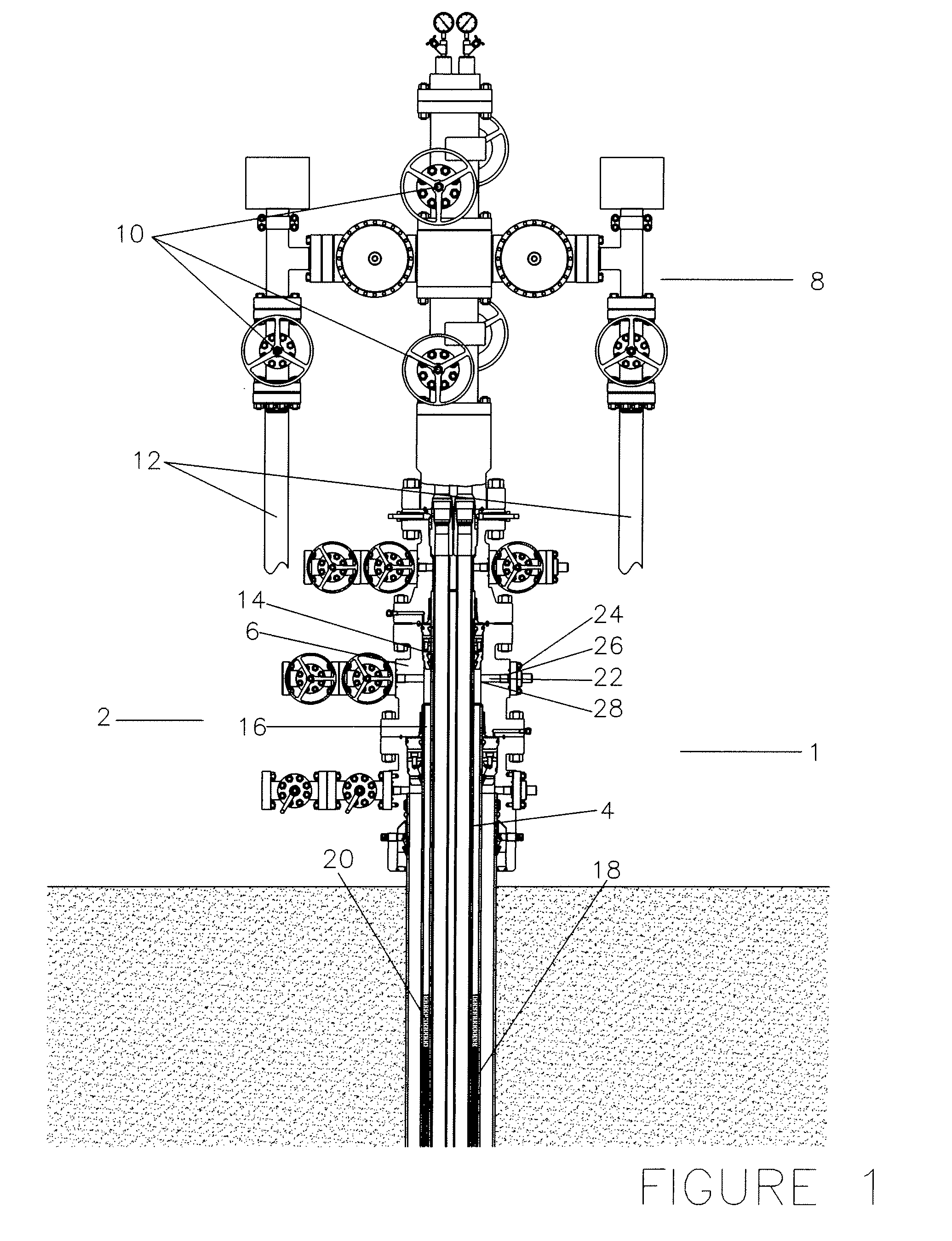
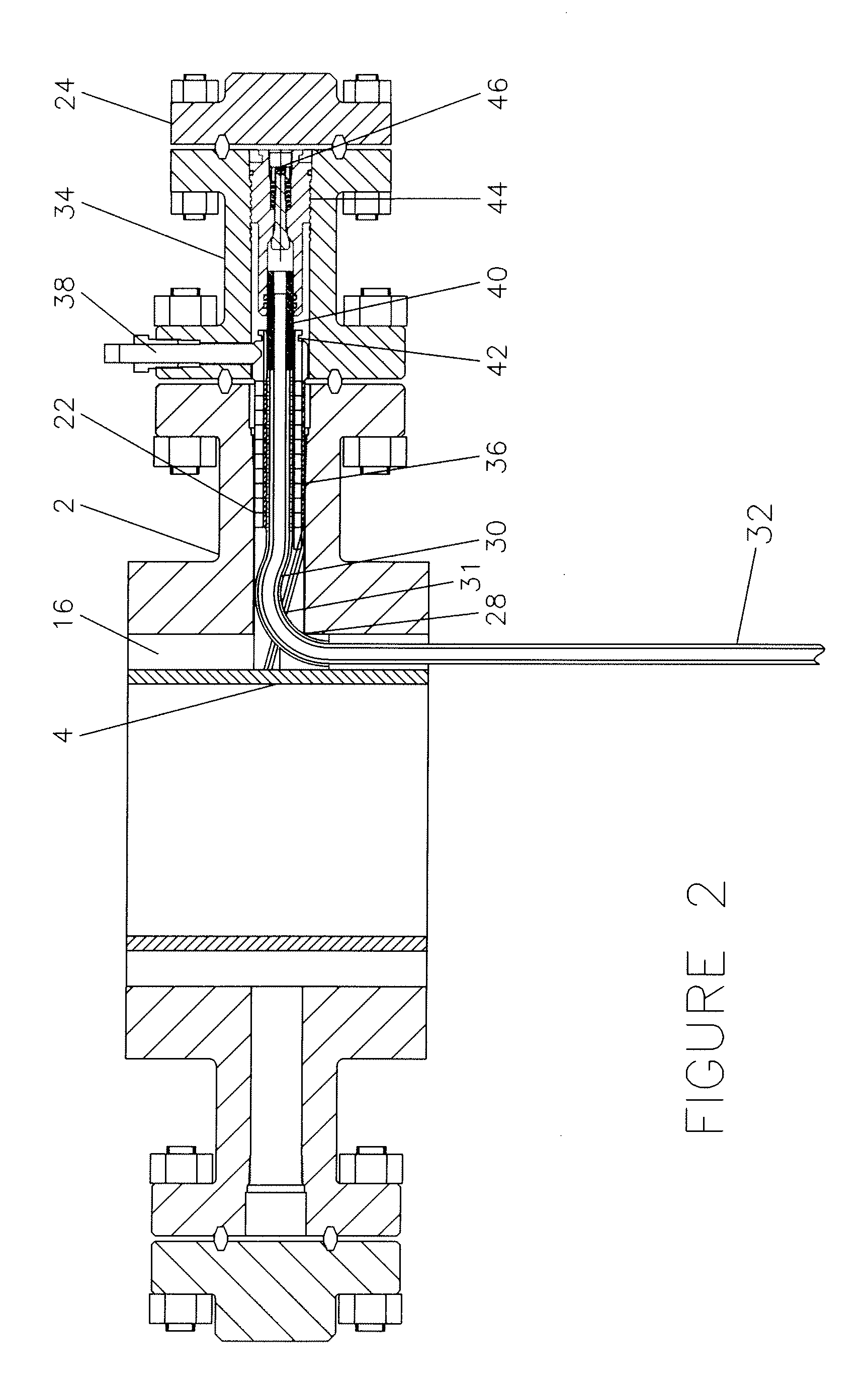
[0029]FIG. 1 is a drawing showing an oil or gas well 1 being produced through a traditional surface wellhead system 2 with a casing string 4 hung in a wellhead spool 6. Atop the wellhead system 2 is a Christmas tree 8 which contains valves 10 that operate the various well functions including delivery of oil or gas into the pipeline(s) 12. Casing hanger 14 supports the inner casing string 4 inside a wellhead spool 6 and create a seal at the top of the corresponding outer casing annulus 16. Casing string 4 has been cemented 18 into place and sometimes unwanted fluids 20 enter the casing annulus 16 through porous cement 18 or a leaking casing string 4. It is often necessary to enter a casing annulus 16 to displace or neutralize the unwanted fluids 20. Access to a casing annulus 16 is made through a wellhead outlet bore 22 after removing the blind flange 24 and conventional VR plug 26. The intersection of the wellhead outlet bore 22 and the casing annulus 16 produces a relatively sharp ...


PUM


Abstract

The method of displacing fluids in the annulus between pressurized casing strings inside an active oil or gas well by providing a controlled turndown insert and guides then inserting and retrieving a flexible hose without it folding or buckling while being pushed or pulled through a wellhead system orifice with relatively sharp edges at the annulus opening where the hose must make a 90 degree turn from horizontal to vertical within a short radius without cutting, crimping or tearing the hose then seating and holding the hose while fluids are injected, all the while providing protection against well blow out or other pressure problems.

Description

CROSS-REFERENCE TO RELATED APPLICATIONS[0001]N / ASTATEMENT REGARDING FEDERALLY SPONSORED RESEARCH OR DEVELOPMENT[0002]N / AINCORPORATION-BY-REFERENCE OF MATERIAL SUBMITTED ON A COMPACT DISK[0003]N / ABACKGROUND OF THE INVENTION[0004]The field of this invention is that of inserting and retrieving several thousand feet of a flexible hose from a horizontal opening into the narrow annulus between casing strings of oil or gas wells. The hose will be inserted through the wellhead outlet bore that has relatively sharp corners at the annulus opening. The hose bend radius required at the annulus opening where the casing annulus and the wellhead outlet bore intersect is a very tight turn requiring the hose to turn from horizontal to vertical in the distance of approximately 1.25 inches. When hoses are inserted they are cut or crimped by the sharp corners at the annulus opening (intersection) and are rendered useless and / or can not be retrieved because they will be severed by the sharp corners. The...

Claims


Application Information

Patent Timeline
Patent Type & Authority Applications(United States)
IPC IPC(8): E21B41/00E21B23/00
CPCE21B19/22E21B33/068E21B21/00
Inventor BAUGH, BENTON F.
Owner VETCO GRAY
Why Eureka
Try Eureka