Pothole patching machine

a pothole and automatic technology, applied in the direction of roads, in situ paving, roads, etc., can solve the problems of no control over the amount of tamping and/or pressure, difficult directing of patching material into the hole, and waste of patching material

Active Publication Date: 2010-12-23
RYAN KEITH A
View PDF20 Cites 22 Cited by
  • Summary
  • Abstract
  • Description
  • Claims
  • Application Information

AI Technical Summary

Problems solved by technology

The draw back to the Heliesko device is that directing the patching material into the hole can be somewhat difficult and likely creates a lot of patch material waste.
Secondly...

Method used


Image

  • Pothole patching machine
  • Pothole patching machine
  • Pothole patching machine

Examples


Embodiment Construction

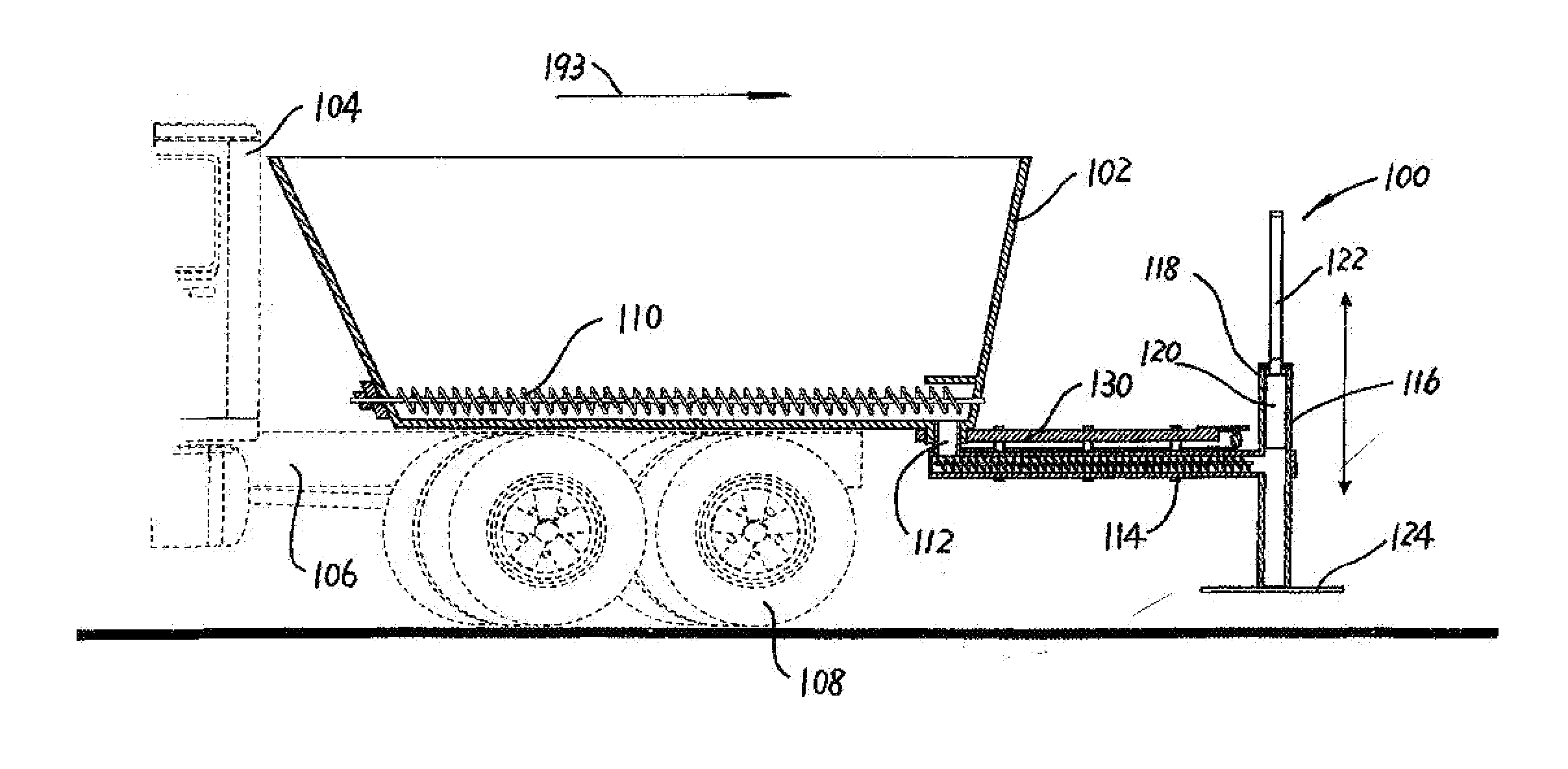
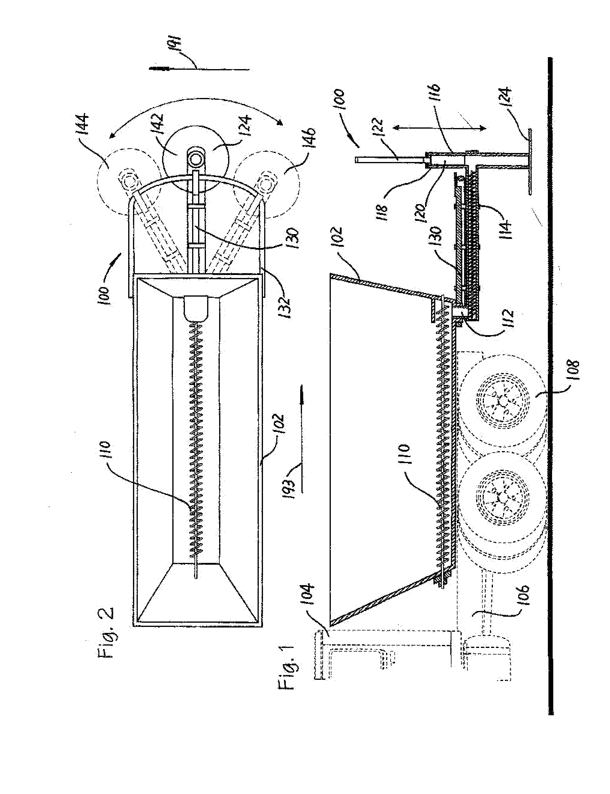
[0015]Referring first of all to FIGS. 1 through 5, pothole patching machine 100 includes the following major components namely a container 102 which is mounted onto a vehicle 104 which is not part of the pothole patching machine but is shown in dashed lines to understand that the pothole patching machine 100 can be deployed onto a vehicle 104. Vehicle 104 normally some type of a truck usually contains a truck frame 106 and truck wheels 108.

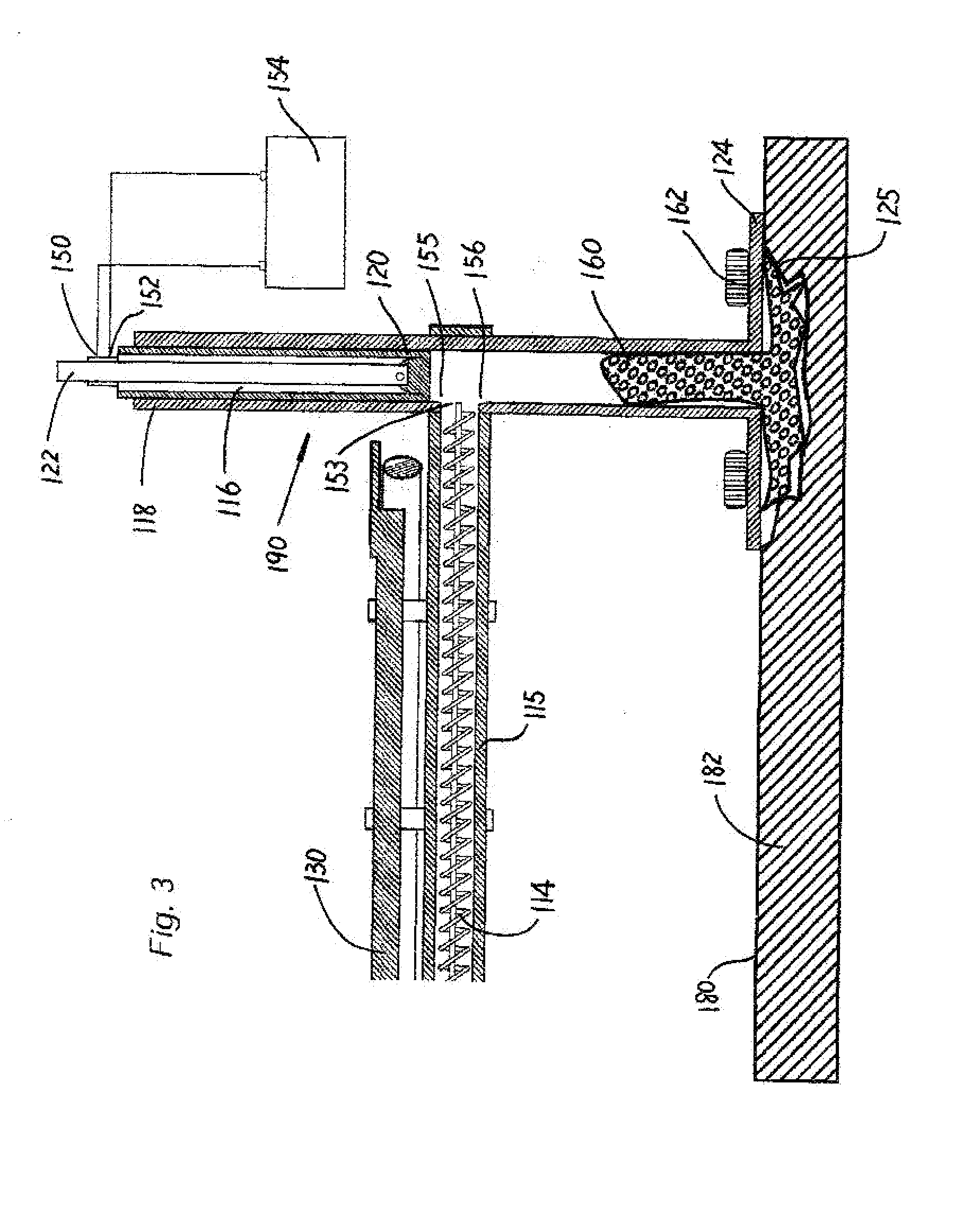
[0016]Container 102 is normally mounted onto truck frame 106 and will hold patching material not shown in the diagrams. Container 102 may include a heating device not shown in order to maintain the content of container 102 at a predetermined temperature. Patch material 160 can be in the form of hot asphalt or a mixture of liquid rubber and asphalt and / or any other suitable composition which is useful for patching potholes 125 in pavements 182. Container 102 has mounted therein an auger 110 which feeds the patch material into a discharge port 112...


PUM


Abstract

A pothole patching machine includes a container for storage of patch material, and a auger screw conveyor for conveying the patch material from the container to a ram. The ram is adapted to forcibly urge the patch material into a pothole. The ram is moveable between a retracted position and an extended position which completes one fill stroke. The ram also includes a foot plate dimensioned for positioning over the pothole and sensors for sensing when the pothole has been filled.

Description

[0001]The applicant claims priority from U.S. provisional patent application 61 / 218,126 titled POTHOLE PATCHING MACHINE, which was filed on Jun. 18, 2009 by Bill Ryan.FIELD OF THE INVENTION[0002]The present device relates generally to machines used to fill potholes in paved roads and more particularly relates to a semi-automated pothole patching machine.BACKGROUND OF THE INVENTION[0003]U.S. Pat. No. 5,131,788 entitled Mobile Pothole Patching Vehicle filed by Leslie Huliesko issued on Jul. 21, 1992 and filed on Sep. 28, 1990. This patent describes a mobile pothole patching vehicle which conveys patching material from a container in a vehicle to the area that needs to be repaired. Thereafter a vehicle mounted tamping device tamps the patched material into the pothole that is to be filled. This machine relies on operator accuracy to ensure that the patching material is placed in the proper location and thereafter a tamper is used to level the material ensuring that there is a smooth su...

Claims


Application Information

Patent Timeline
IPC IPC(8): E01C23/10E01C21/00
CPCE01C23/06
Inventor RYAN, BILL
Owner RYAN KEITH A
Why Eureka
Try Eureka