Myopia control ophthalmic lenses

a technology of ophthalmic lenses and myopia, applied in the field of myopia control ophthalmic lenses, can solve the problems that the design approach suggested does not seem to address specific wavefront/refractive power characteristics of individual eye/or group average data or changes, and achieve the effect of controlling or slowing the progression of myopia

Active Publication Date: 2010-12-30
JOHNSON & JOHNSON VISION CARE INC
View PDF16 Cites 29 Cited by
  • Summary
  • Abstract
  • Description
  • Claims
  • Application Information

AI Technical Summary

Benefits of technology

[0011]In yet another aspect of the invention, a design for an ophthalmic lens produced according to the methods of the invention includes a convex surface with a central optic zone surrounded by a peripheral zone which is further surrounded by an edge zone, and a concave surface which rests on the wearer's eye; the central optic zone contain

Problems solved by technology

The design approach suggested does not appear to address specific wavefront/refractive power character

Method used


Image

  • Myopia control ophthalmic lenses
  • Myopia control ophthalmic lenses
  • Myopia control ophthalmic lenses

Examples


example 1

Prophetic

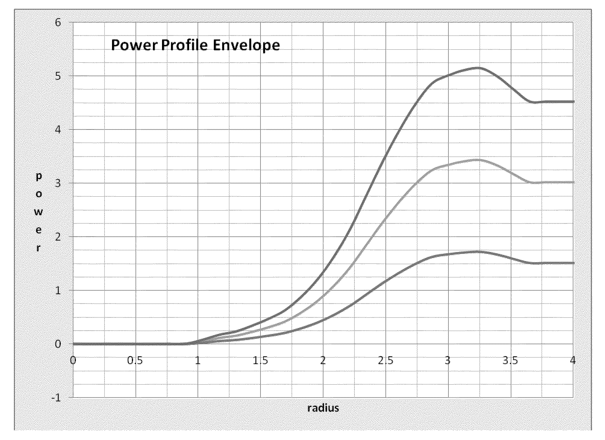
[0100]In a longitudinal study comparing the axial length (eye growth) and auto-refraction of an age matched pediatric population of subjects aged 6 to 14 yrs old, contact lenses produced according to the method and design of the present invention are fitted to one group while a control group wears conventional contact lenses or spectacles. The first group receives lenses according to the following lens design and optical power profile described herein.[0101]a) The optical power in the central disc of the optic zone is substantially constant;[0102]b) the optical power in the first annulus at about a diameter of 4 mm increases in plus power to a range of +0.5 to +1.5 D, with a preferred value of about +1.0 D, at a diameter of 6.5 mm increases in plus power to a range +1.5 to +4.5 D, with a preferred value of about +3.4 D;[0103]c) the optical power in the second annulus decreasing from the power found at the edge of the first annulus to a power between +1.5 and +4.5 D, with a ...


PUM


Abstract

Lenses are designed using the corneal topography or wavefront measurements of the eye derived by subtracting the optical power of the eye after orthokeratology treatment from the optical power before orthokeratology treatment.

Description

BACKGROUND OF THE INVENTION[0001]This invention relates to designs and methods for preventing, stopping or slowing myopia progression.[0002]Myopia, also known as short-sightedness, is a refractive condition wherein the overall power of the eye is too high, or too strong, causing light from distant objects to focus in front of the retina. This is perceived by the viewer as blurring of distant objects, with the amount of blurring being related to the severity of the myopia. This condition is often first seen in childhood, and usually noticed at school age. A progression, or increase, in the severity of myopia, is usually seen in myopic cases until young adulthood.[0003]U.S. Pat. No. 6,045,578 proposes methods of using on-axis longitudinal spherical aberration (LSA) in contact lens designs to attempt to halt myopia progression. The design approach suggested does not appear to address specific wavefront / refractive power characteristics of the individual eye / or group average data or chan...

Claims


Application Information

Patent Timeline
IPC IPC(8): G02C7/04G02C7/02G02C7/06G06F17/10
CPCG02C7/04G02C7/047G02C7/028G02C2202/24G02C7/00G02C7/02G02C7/024G02C7/027
Inventor COLLINS, MICHAEL J.DAVIS, BRETT A.CHEHAB, KHALED A.CHENG, XUISKANDER, D. ROBERT
Owner JOHNSON & JOHNSON VISION CARE INC
Why Eureka
Try Eureka