Two piece upper reciever for firearms

Inactive Publication Date: 2011-01-06
PATRIOT ORDNANCE FACTORY INC
View PDF7 Cites 64 Cited by
  • Summary
  • Abstract
  • Description
  • Claims
  • Application Information

AI Technical Summary

Problems solved by technology

The formation of cross channels in the upper surface of the upper receiver thins the material of the upper receiv

Method used


Image

  • Two piece upper reciever for firearms
  • Two piece upper reciever for firearms
  • Two piece upper reciever for firearms

Examples


Embodiment Construction

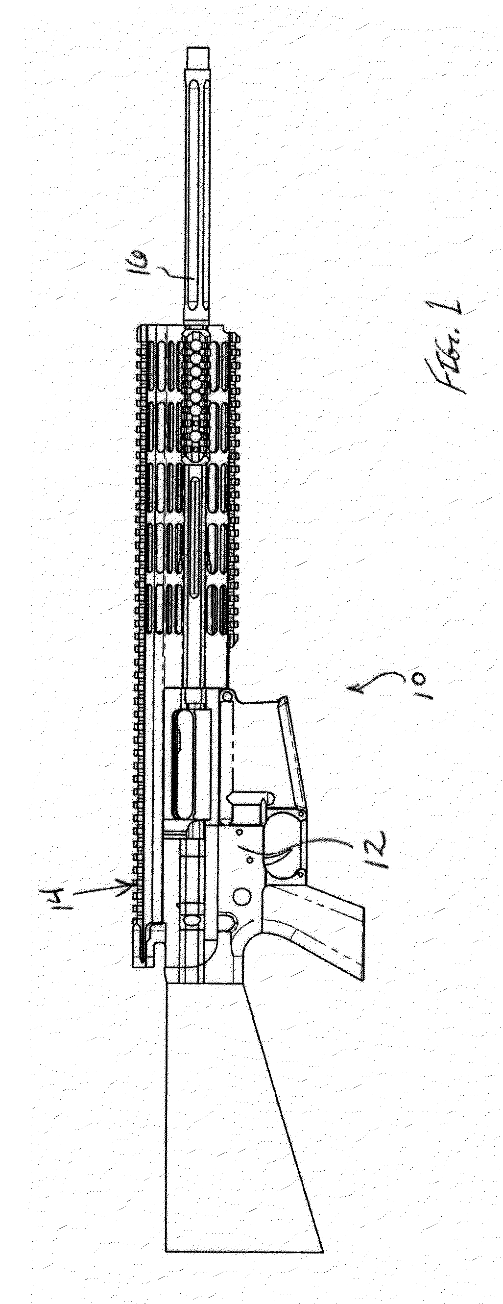
[0018]Turning now to the drawings in which like reference characters indicate corresponding elements throughout the several views, attention is first directed to FIG. 1 which illustrate a firearm generally designated 10. Firearm 10 includes a lower receiver 12, a two piece upper receiver 14 carried by lower receiver 12, and a barrel 16 coupled to two piece upper receiver 14. In the preferred embodiment, firearm 10 is an auto-loading rifle of the AR10, AR15 or M16 type.

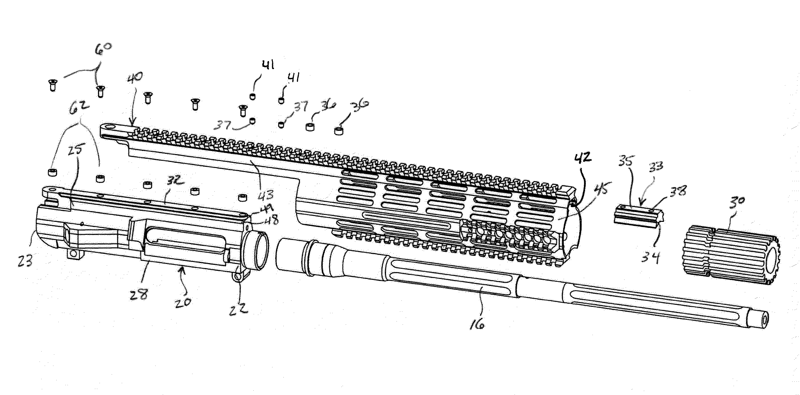
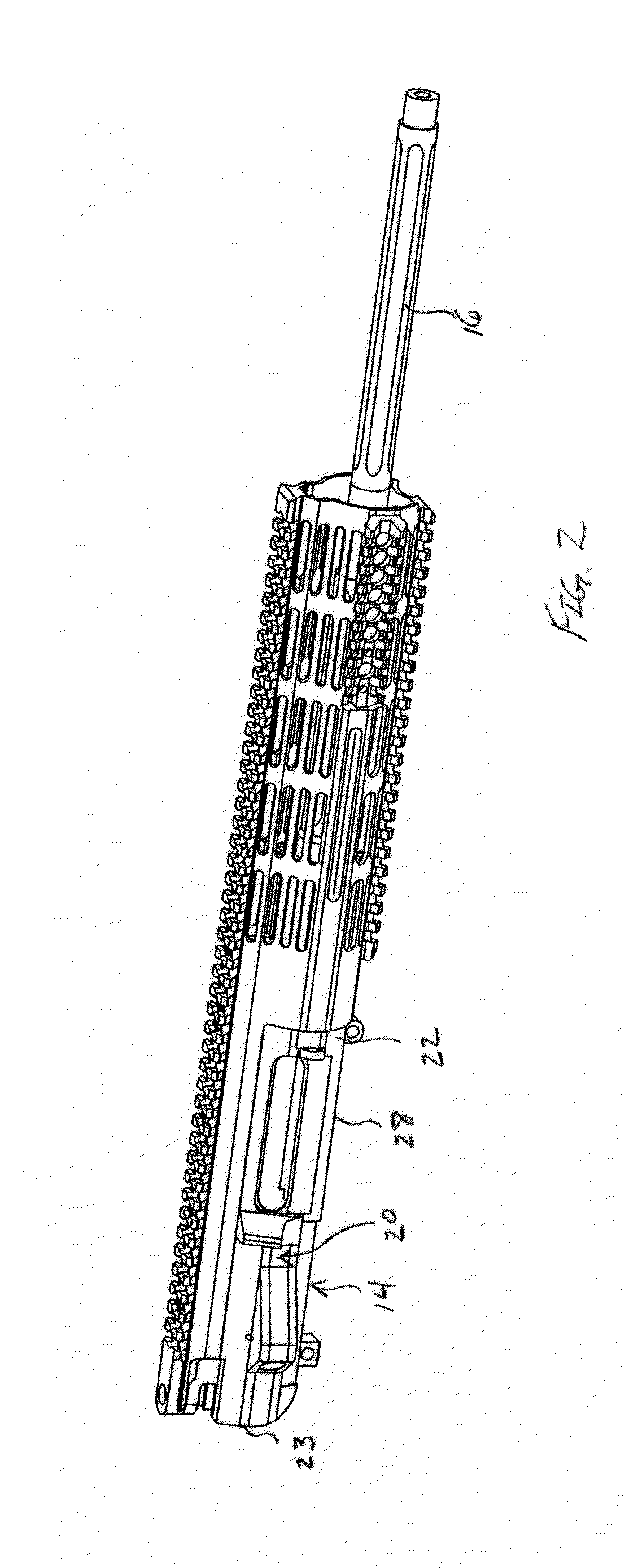
[0019]Turning now to FIGS. 2-5, two piece upper receiver 14 for firearm 10 is illustrated. Two piece upper receiver 14 includes a first piece 20 having a front end 22, a rear end 23, a top 25, and a bottom 28. First piece 20 is constructed to operatively carry a bolt carrier and bolt. These elements are not described in detail as they are conventionally known and used in this application. The novelty lies in the unique two piece construction of two piece upper receiver 14. Barrel 16 is coupled to front end 22 with a ba...


PUM


Abstract

A two piece upper receiver for a firearm including a first piece having a front end, a rear end, a top, and a bottom, the first piece constructed to operatively carry a bolt carrier and bolt, and to have a barrel coupled to the front end. The bottom is constructed to have a lower receiver coupled thereto. The first piece includes a backbone extending along the top between the front end and the rear end, the back bone having upwardly directed indexing surfaces. A second piece overlies the backbone and includes mating surfaces engaging the indexing surfaces, aligning the second piece with the first piece. A receiving structure is opposite the mating surfaces for receiving accessory devices mounted thereon. Fasteners fixedly attach the second piece to the first piece to form a complete upper receiver.

Description

FIELD OF THE INVENTION[0001]This invention relates to firearms.[0002]More particularly, the present invention relates to firearms having an upper receiver coupled to a lower receiver.BACKGROUND OF THE INVENTION[0003]In the field of firearms, and specifically AR10, AR15 or M16 type firearms, various accessories for sighting to improve putting bullet on target, are employed. These sighting devices must be securely, rigidly and accurately attached to a firearm. To this end, firearms include an upper receiver formed of a single piece and having an upper surface designed to receive various sighting devices. The upper surface is formed as a rail for receiving and registering sighting devices. While effective, the typical rail is a Picatinny rail type that includes cross channels used for receiving and registering the sighting devices attached thereto. The formation of cross channels in the upper surface of the upper receiver thins the material of the upper receiver and can adversely affec...

Claims


Application Information

Patent Timeline
IPC IPC(8): F41A21/00F41A21/48F41C27/00
CPCF41A3/66F41G11/003F41G1/387F41C23/16
Inventor DESOMMA, FRANKDAVIES, ROBERT B.
Owner PATRIOT ORDNANCE FACTORY INC
Why Eureka
Try Eureka