
Apparatus and Method for Ferroelectric Conversion of Heat to Electrical Energy

a technology of ferroelectrics and electrical energy, applied in the direction of electrical apparatus, thermal electric motors, generators/motors, etc., can solve the problems of impede the more powerful energy conversion that can be achieved with ferroelectrics, variable capacitors do not effectively exploit the power inherent spontaneous polarization, and variable capacitors do not effectively convert heat to electricity. , to achieve the effect of robust heat conversion

Inactive Publication Date: 2011-01-06
THE NEOTHERMAL ENERGY
View PDF18 Cites 11 Cited by
  • Summary
  • Abstract
  • Description
  • Claims
  • Application Information

AI Technical Summary

Benefits of technology

This approach allows for a robust and efficient conversion of heat to electrical energy, exceeding the energy generated by prior methods that rely on external fields, with the potential for high voltage output and broad applicability across various temperature ranges.

Problems solved by technology

The variable capacitor method of converting heat to electricity is not the most effective method of using ferroelectrics to generate electricity, however.
Variable capacitors do not effectively exploit the powerful inherent spontaneous polarization that occurs in ferroelectrics without an applied field.
Further, the application of large external fields and the continuous application of an external field during cycling impede the more powerful energy conversion that can be achieved with ferroelectrics.
Such external fields prevent the effective use of the tremendous electrical energy that arises from the electric dipoles of ferroelectric materials spontaneously and without induction by an external field.
Therefore, a heretofore unaddressed need exists in the art to address the aforementioned deficiencies and inadequacies.

Method used


Image

  • Apparatus and Method for Ferroelectric Conversion of Heat to Electrical Energy
  • Apparatus and Method for Ferroelectric Conversion of Heat to Electrical Energy
  • Apparatus and Method for Ferroelectric Conversion of Heat to Electrical Energy

Examples


Embodiment Construction

[0079]The present invention is more particularly described in the following examples that are intended as illustrative only since numerous modifications and variations therein will be apparent to those skilled in the art. Various embodiments of the invention are now described in detail. Referring to the drawings, like numbers indicate like components throughout the views. As used in the description herein and throughout the claims that follow, the meaning of “a”, “an”, and “the” includes plural reference unless the context clearly dictates otherwise. Also, as used in the description herein and throughout the claims that follow, the meaning of “in” includes “in” and “on” unless the context clearly dictates otherwise. Additionally, some terms used in this specification are more specifically defined below.

[0080]The terms used in this specification generally have their ordinary meanings in the art, within the context of the invention, and in the specific context where each term is used....


PUM


Abstract

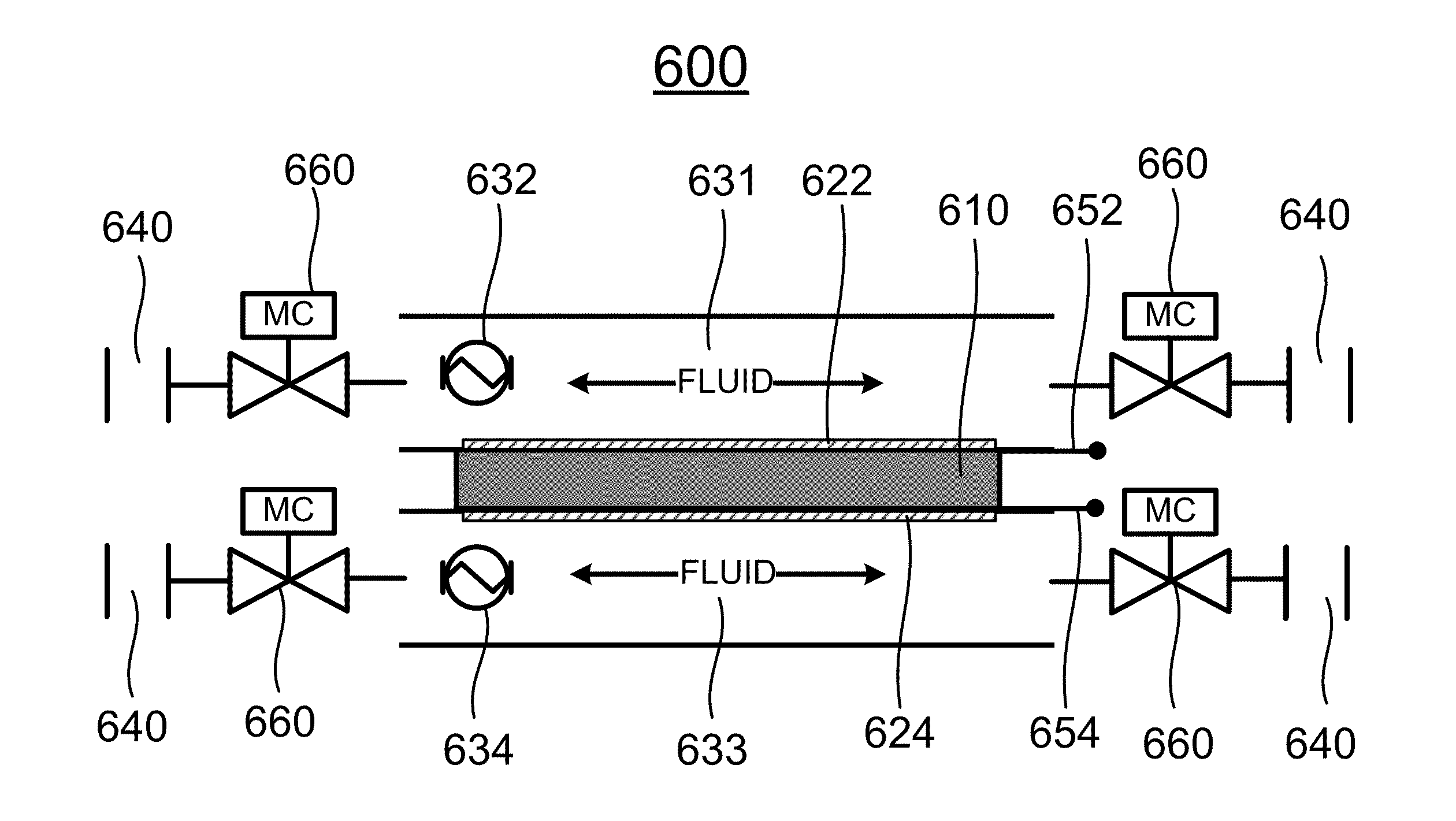
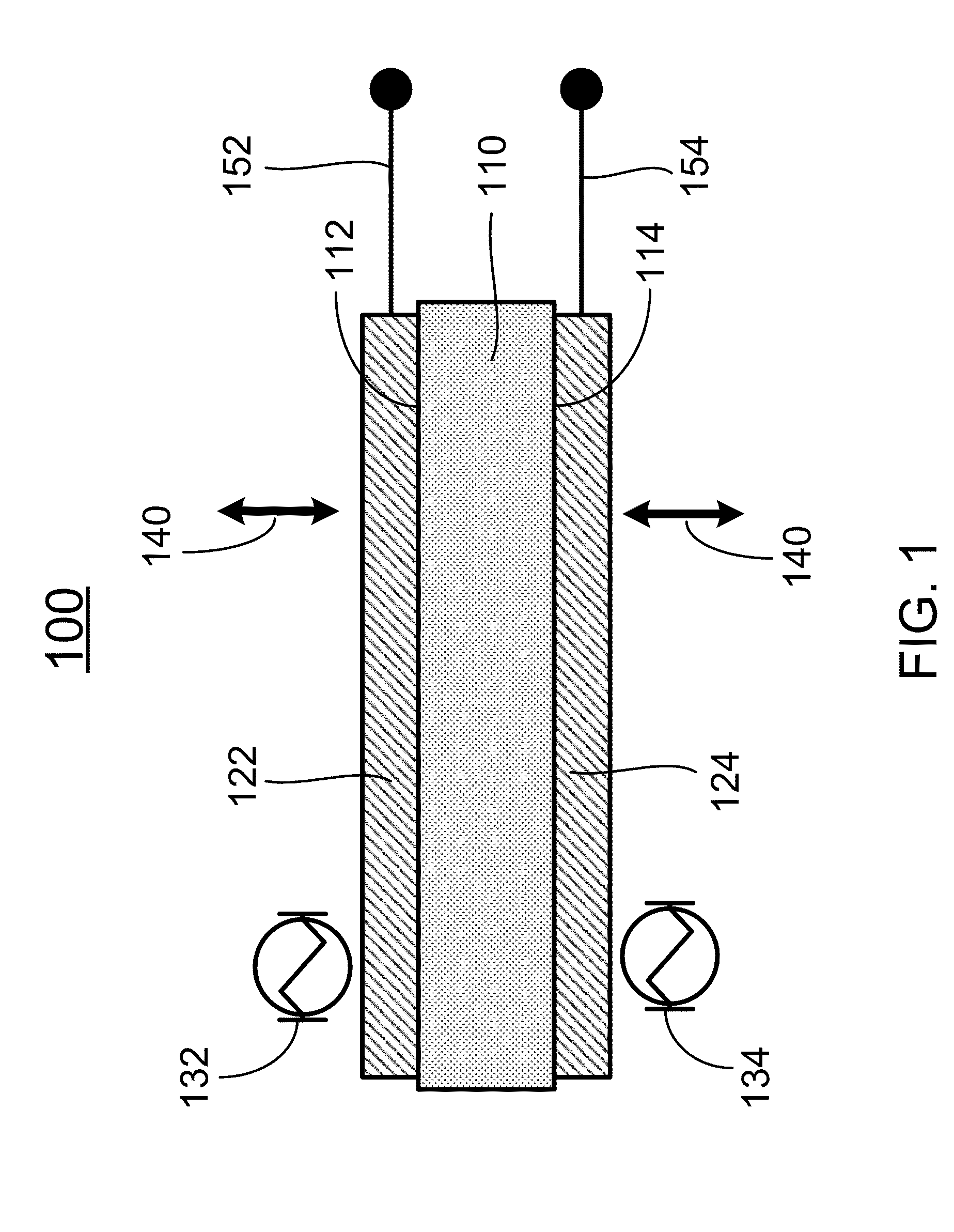
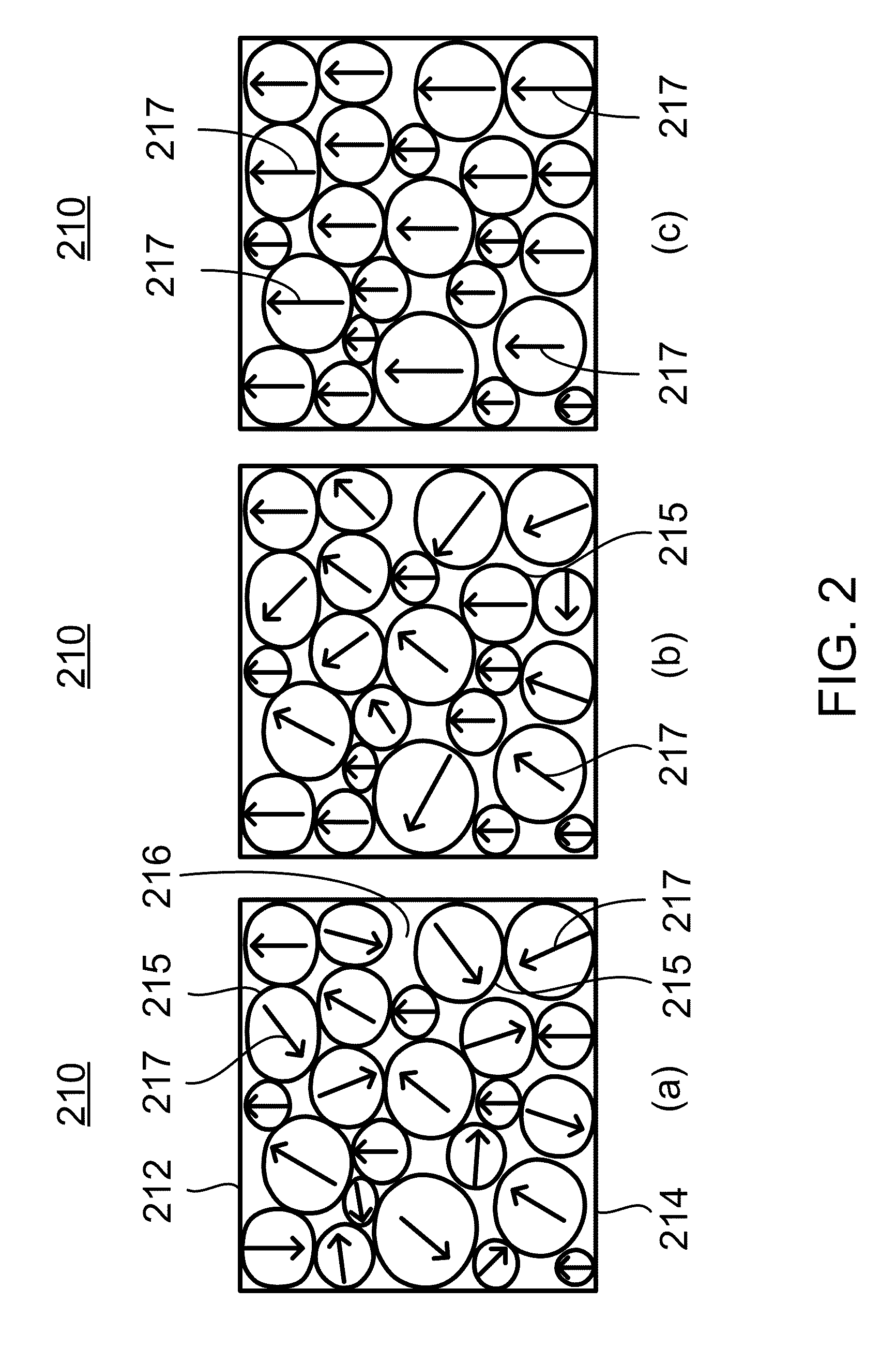
The present invention relates to a new method and apparatus for converting heat to electric energy. The invention exploits the rapid changes in spontaneous polarization that occur in ferroelectric materials during phase change. The invention permits robust and economical generation of electric energy from thermal energy, and it can be used in many different applications. In one aspect, the present invention relates to an apparatus for converting heat to electric energy comprising a pair of electrodes; a ferroelectric layer formed there between with a ferroelectric material characterized with a Curie temperature, Tc, such that when the temperature of the ferroelectric material is lower than Tc, the ferroelectric material is in a ferroelectric phase in which very powerful polarization is established spontaneously in the unit cells of the ferroelectric material, and when the temperature of the ferroelectric material is greater than Tc, spontaneous polarization is not established in the unit cells of the ferroelectric material; and a means for alternately delivering a flow of cold fluid and a flow of hot fluid to the ferroelectric layer so as to alternately cool the ferroelectric layer at a first temperature TL that is lower than Tc, and heat the ferroelectric layer at a second temperature TH that is higher than Tc, thereby the ferroelectric material of the ferroelectric layer undergoes alternating phase transitions between the ferroelectric phase and the paraelectric phase with temperature cycling.

Description

CROSS-REFERENCE TO RELATED PATENT APPLICATION[0001]This application is a continuation application of a U.S. application Ser. No. 12 / 465,924, filed May 14, 2009, entitled “APPARATUS AND METHOD FOR FERROELECTRIC CONVERSION OF HEAT TO ELECTRICAL ENERGY,” by Ahmet Erbil and David F. Walbert, which is incorporated herein by reference in its entirety.[0002]Some references, which may include patents, patent applications and various publications, are cited and discussed in the description of this invention. The citation and / or discussion of such references is provided merely to clarify the description of the present invention and is not an admission that any such reference is “prior art” to the invention described herein. All references cited and discussed in this specification are incorporated herein by reference in their entireties and to the same extent as if each reference were individually incorporated by reference.FIELD OF THE INVENTION[0003]The present invention generally relates to ...

Claims


Application Information

Patent Timeline
Patent Type & Authority Applications(United States)
IPC IPC(8): H02N10/00H10N15/10
CPCH01L37/02H10N15/10
Inventor ERBIL, AHMETWALBERT, DAVID F.
Owner THE NEOTHERMAL ENERGY
Learn More