Braking force control device for vehicles

a control device and brake technology, applied in the direction of braking systems, instruments, analogue processes for specific applications, etc., can solve the problems of device problems, poor deceleration feel, occurrence of poor deceleration feel, etc., to avoid poor deceleration feel and high deceleration control responsiveness

Active Publication Date: 2011-01-06
NISSAN MOTOR CO LTD
View PDF6 Cites 16 Cited by
  • Summary
  • Abstract
  • Description
  • Claims
  • Application Information

AI Technical Summary

Benefits of technology

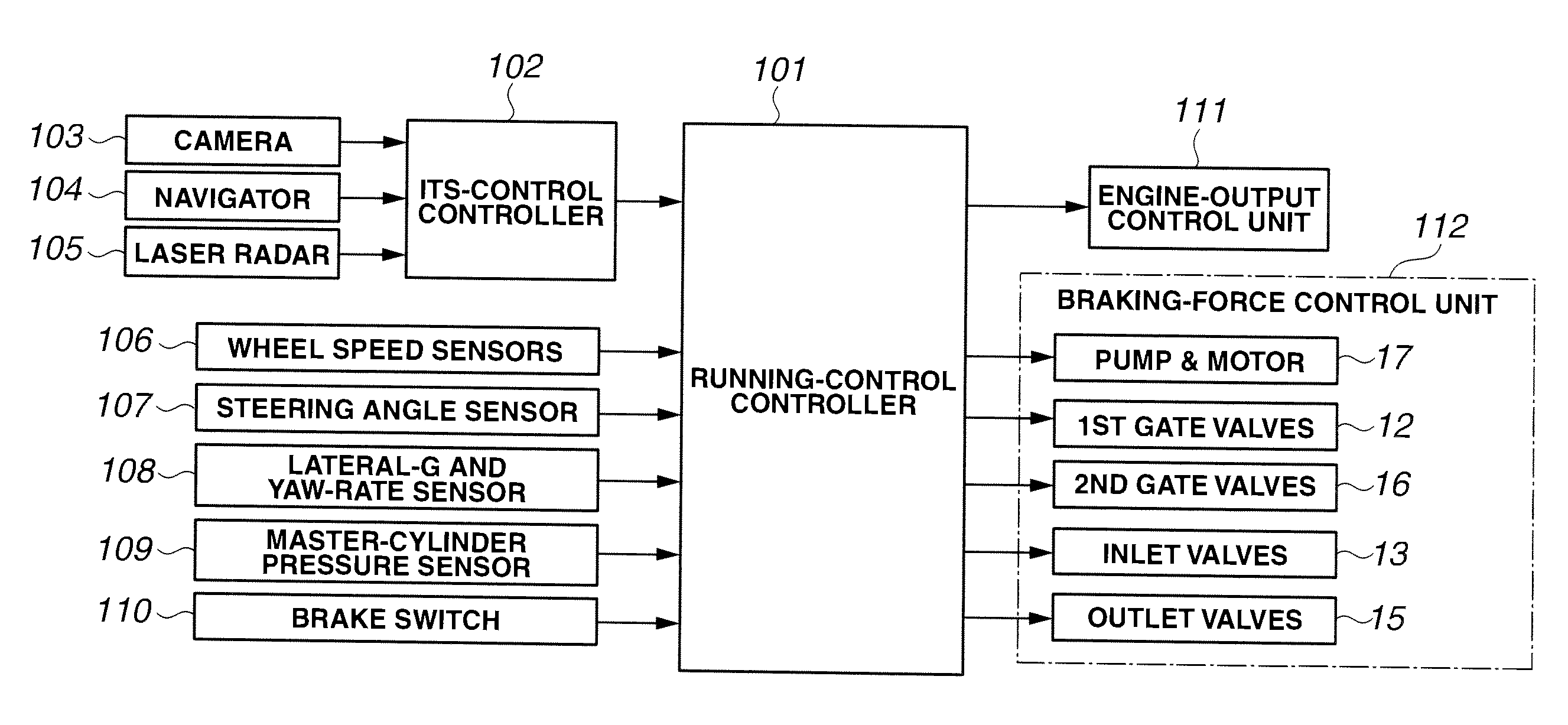
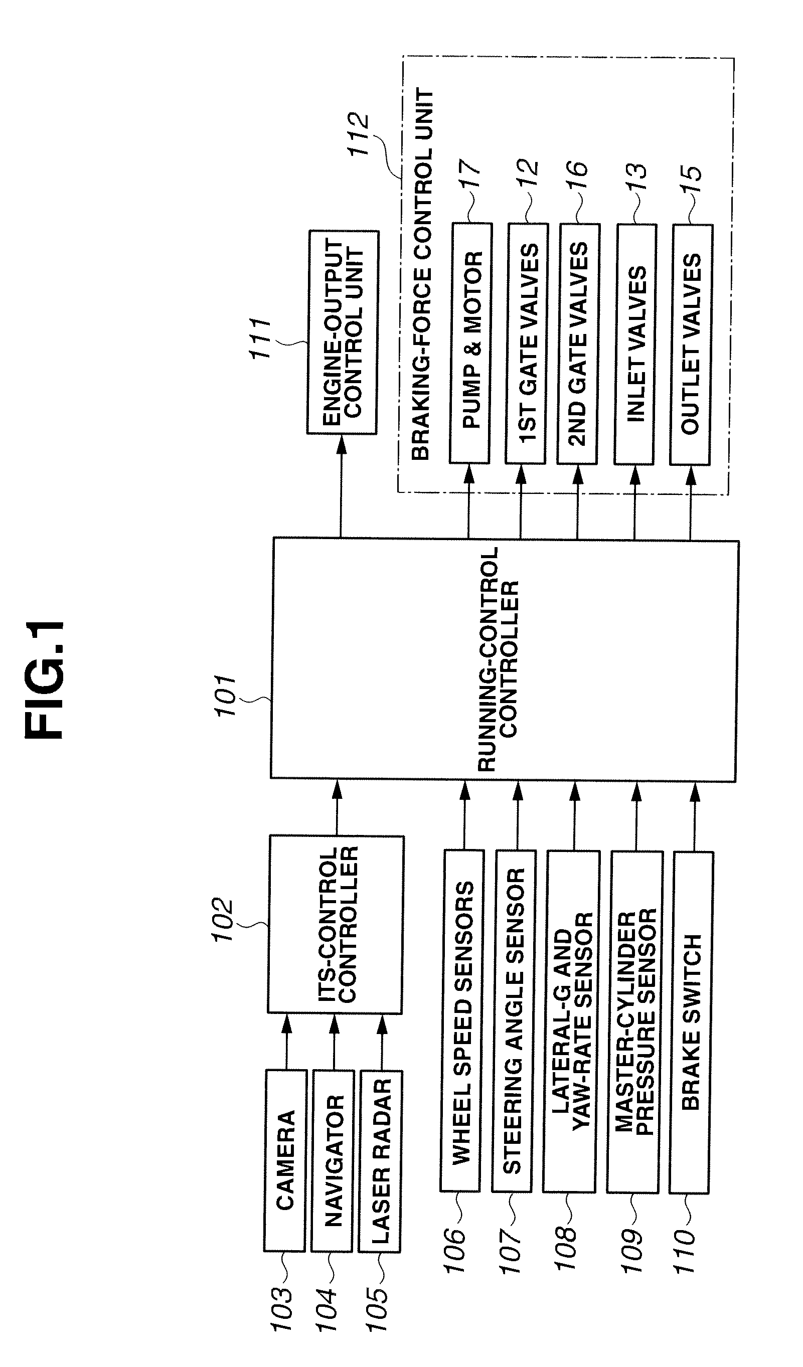
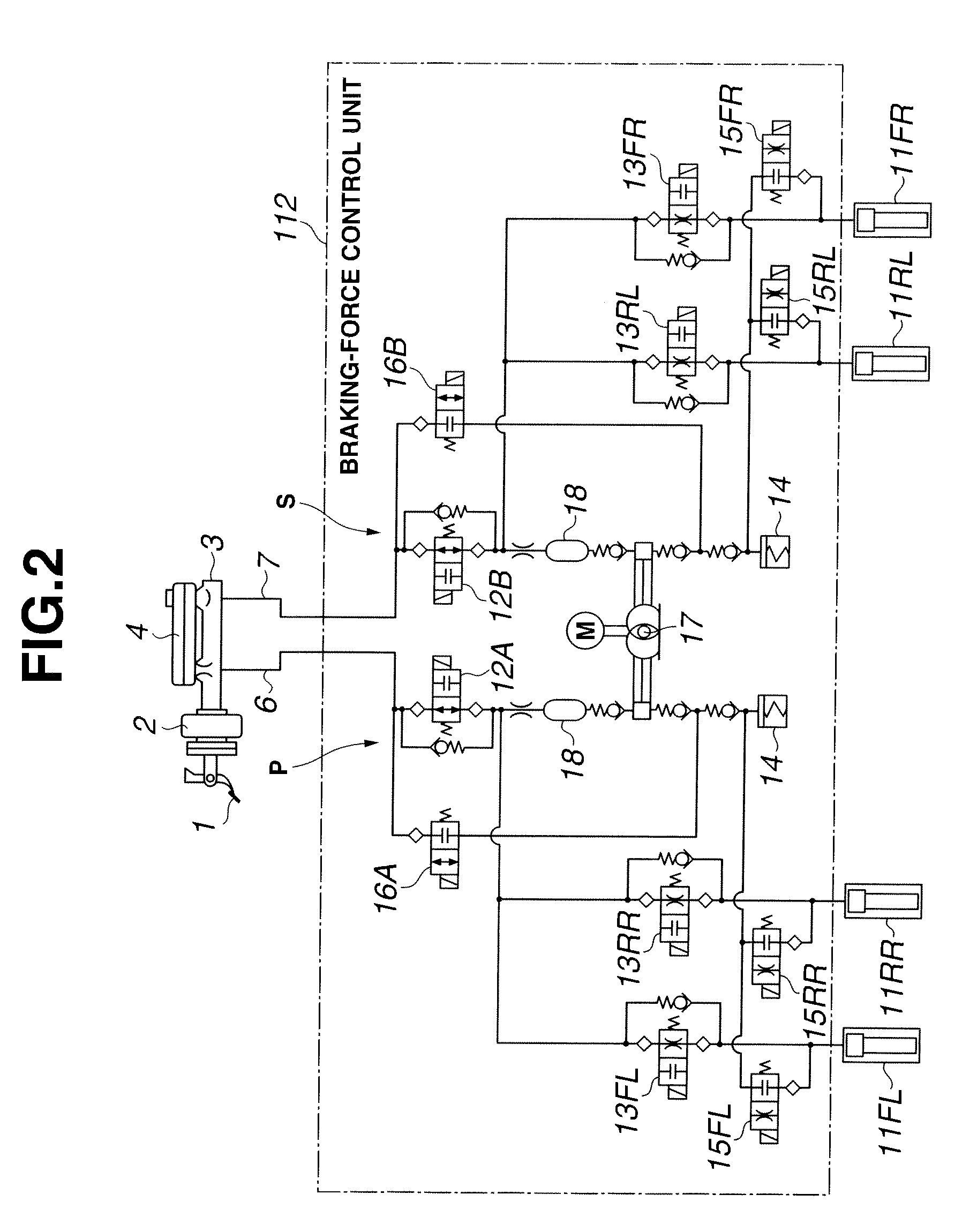
[0005]It is, therefore, in view of the previously-described drawbacks of the prior art, an object of the invention to provide a braking force control device having a high deceleration control responsiveness and configured to avoid a poor deceleration feel that can be caused during a mode shift from an automatic brake mode to a manual brake mode and also to avoid an uncomfortable brake-pedal drawn-in feeling that can be caused during a mode shift from a manual brake mode to an automatic brake mode.

Problems solved by technology

However, in the prior art automatic brake device as described previously, the automatic brake function becomes canceled or deactivated when a transition from the automatic brake state to the driver's manual brake state occurs.
Hence, the device has a problem as hereunder discussed.
This leads to the problem of the occurrence of a poor deceleration feel.

Method used


Image

  • Braking force control device for vehicles
  • Braking force control device for vehicles
  • Braking force control device for vehicles

Examples


Embodiment Construction

[0019]Therefore, according to the braking-force control device of the invention, a comparison between a braking force created by a manual brake device and a required braking force for an automatic brake device is made, and then the automatic brake device is selectively actuated when the required braking force exceeds in braking-force magnitude. That is, it is possible to selectively execute a brake mode having a higher one of the braking force created by the manual brake device and the required braking force for the automatic brake device. Therefore, even when the braking force created by the driver's manual brake is less than the braking force for the automatic brake, the automatic brake device comes into operation so as to achieve the required braking force, thus eliminating a poor deceleration feel.

[0020]Additionally, when the time rate of change in the braking force difference is great, a reducing amount of the required braking force for the automatic brake device can be reduced...


PUM


Abstract

A controller of a braking force control device for vehicles is characterized by comprising an automatic-brake selective-actuation section configured to compare a braking force created by a manual brake device with a required braking force for an automatic brake device and to selectively actuate the automatic brake device when the required braking force exceeds in braking-force magnitude, a braking-force-difference time-rate-of-change calculation section configured to calculate a braking-force-difference time rate of change corresponding to a rate of change per unit time in a difference, which difference is obtained by subtracting the required braking force for the automatic brake device from the braking force created by the manual brake device, and a required braking force control section configured to correct the required braking force for the automatic brake device in a manner so as to reduce the required braking force when selectively actuating the automatic brake device. Also, a reducing amount of the required braking force is corrected to decrease, as the calculated braking-force-difference time rate of change increases.

Description

TECHNICAL FIELD[0001]The present invention relates to the control of a hydraulic brake system in which a manual brake, actuated by a driver's operation, and an automatic brake, automatically actuated without driver's operation, are combined with each other.BACKGROUND ART[0002]A driver's brake-pedal depression occurring during operation of the automatic brake, gives the driver an uncomfortable feeling that the brake pedal is undesirably forced to move down and thus drawn in, due to a less brake-pedal reaction force or an insufficient reaction force weakened as compared to a normal brake-pedal reaction force.[0003]For the purpose of eliminating such an uncomfortable feeling, an automatic brake device, described in a patent document 1, is configured to produce a brake fluid pressure by actuating an automatic brake means, when it is determined that a great deceleration is required to avoid a collision of a host vehicle with a preceding vehicle ahead of the host vehicle, or when it is de...

Claims


Application Information

Patent Timeline
Patent Type & Authority Applications(United States)
IPC IPC(8): B60T8/17G06F19/00B60T7/12B60T7/02
CPCB60T7/12B60T2201/02B60T13/147B60T8/4872
Inventor ISHIMOTO, TAKESHI
Owner NISSAN MOTOR CO LTD
Why Eureka
Try Eureka