
Nonconductive antenna mount

a technology of non-conductive and antenna mounts, applied in the direction of pivotable antennas, antenna details, antennas, etc., can solve the problem that significant numbers of potential users remain substantially incapable of deploying satellite antennas

Active Publication Date: 2011-02-10
DISH TECH L L C
View PDF18 Cites 19 Cited by
  • Summary
  • Abstract
  • Description
  • Claims
  • Application Information

AI Technical Summary

Problems solved by technology

While the limited size of the antenna has resulted in a large potential subscriber base, significant numbers of potential users remain substantially incapable of deploying a satellite antenna due to the environment surrounding their home.

Method used


Image

  • Nonconductive antenna mount
  • Nonconductive antenna mount
  • Nonconductive antenna mount

Examples


Embodiment Construction

The enclosed drawings and the following description depict specific embodiments of the invention to teach those skilled in the art how to make and use the best mode of the invention. For the purpose of teaching inventive principles, some conventional aspects have been simplified or omitted. Those skilled in the art will appreciate variations of these embodiments that fall within the scope of the invention. Those skilled in the art will also appreciate that the features described below can be combined in various ways to form multiple embodiments of the invention. As a result, the invention is not limited to the specific embodiments described below, but only by the claims and their equivalents.

In addition, directional references employed below, such as “up”, “down”, “left”, “right”, “back”, “front”, “upper”, “lower”, and so on, are provided to relate various aspects of the structures to each other, and are not intended to limit the embodiments disclosed herein to a particular orientat...


PUM


Abstract

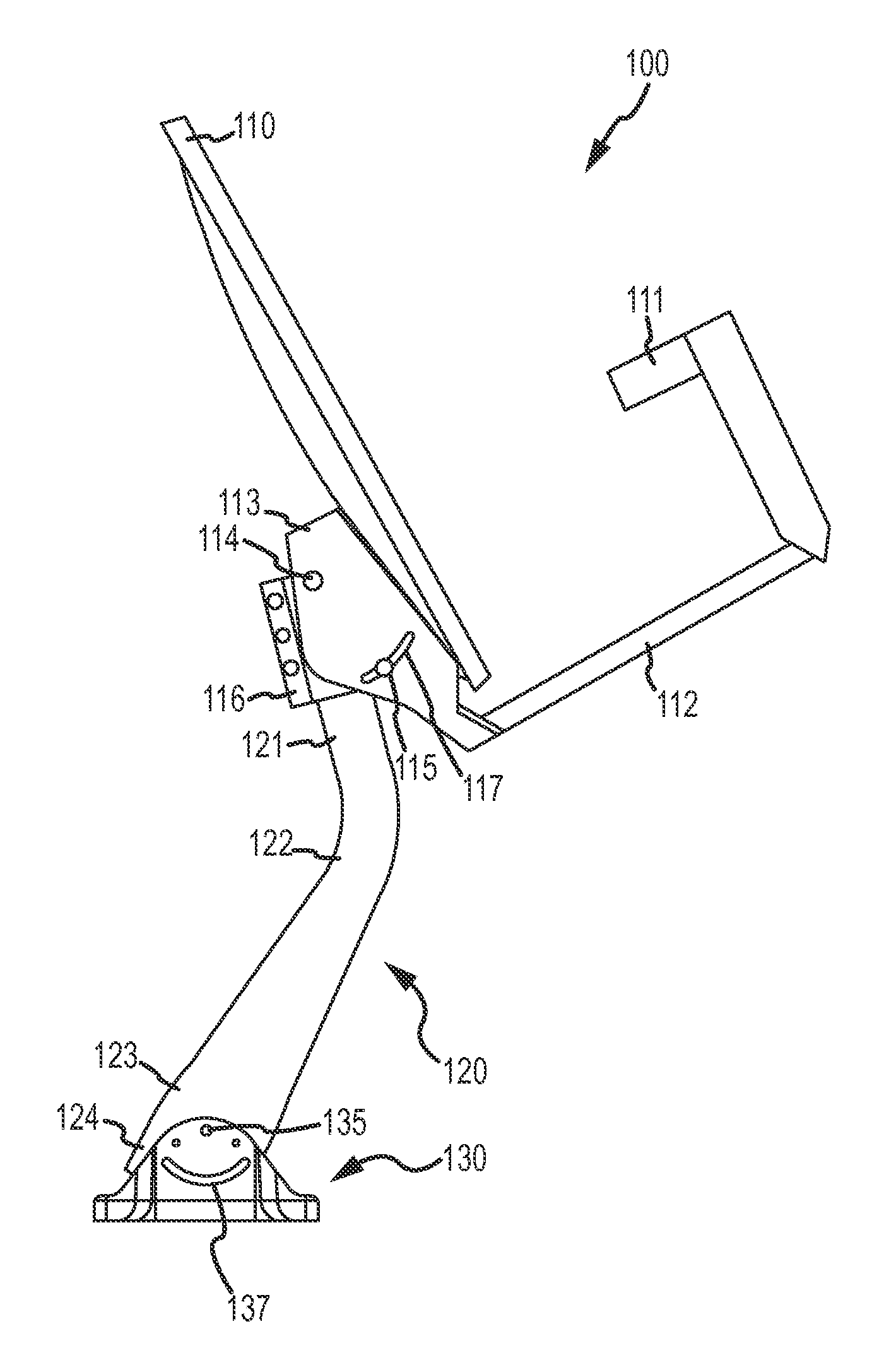
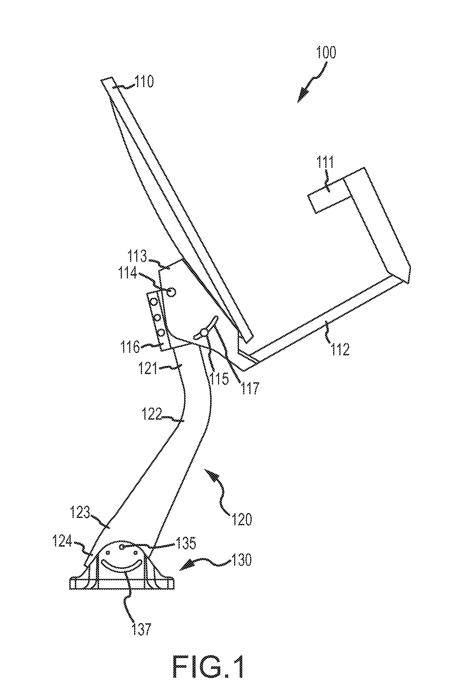
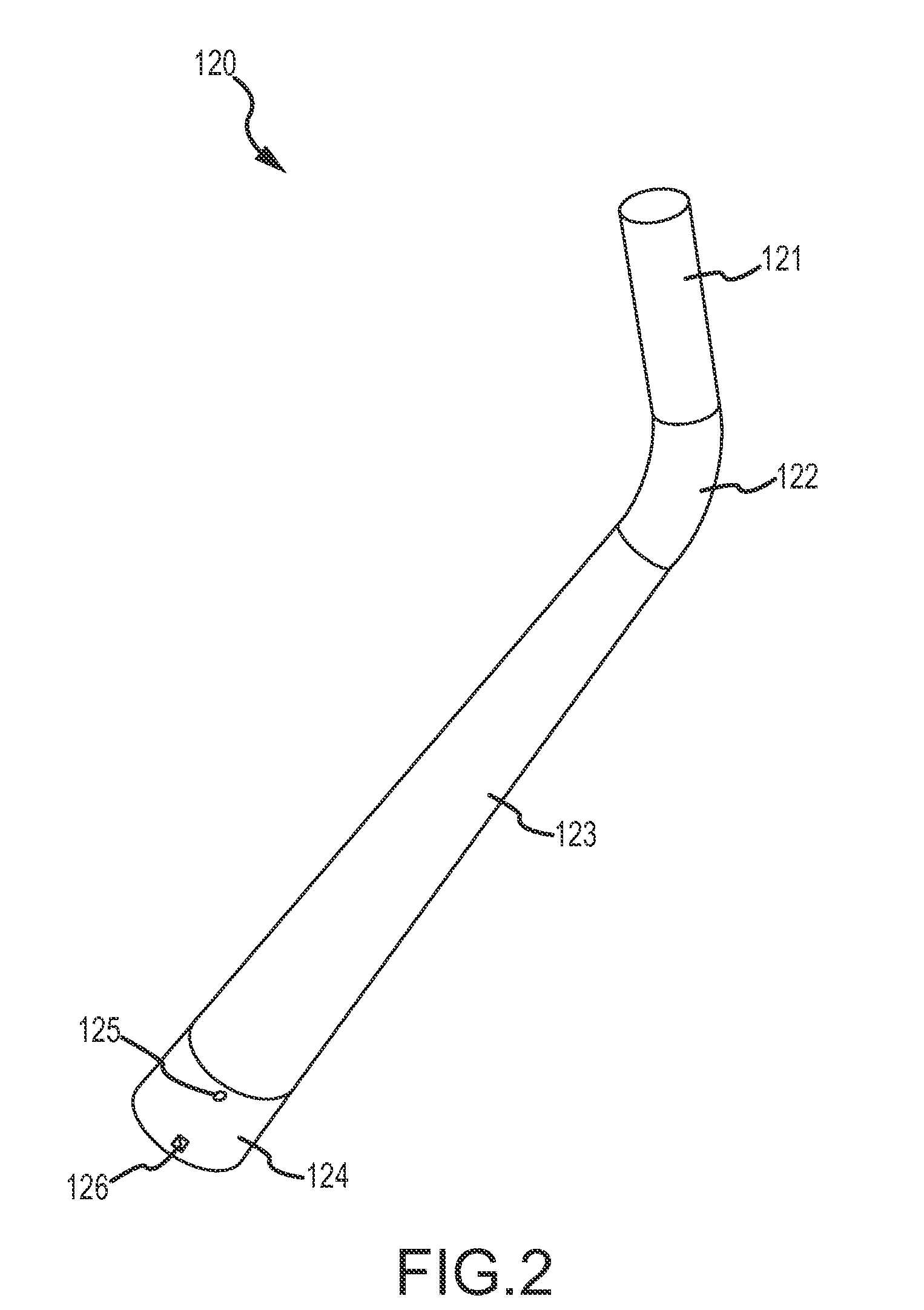
An antenna mount is disclosed. The antenna mount includes a mast and a foot that are substantially free of electrically conductive elements. The mast has a first end having a circular cross-section configured to be received by a mounting bracket of a satellite dish having a circular interior cross-section. The foot is configured to be secured to a stationary mounting surface and to be pivotally attached to a second end of the mast.

Description

BACKGROUNDWith the introduction of direct-to-home satellite broadcast television systems, such as Direct Broadcast Satellite (DBS) systems, a multitude of television programs, audio channels, and the like previously unknown with terrestrial (“over-the-air”) broadcast systems was made accessible to millions of potential subscribers. One aspect of such systems that allows such wide accessibility is the use of a small (e.g., less than one meter in diameter) and inexpensive satellite antenna, or “dish”. To effectively employ such an antenna, a subscriber merely provides direct line-of-sight between the dish and the satellites of interest, and supplies a stable mounting platform or base to which the antenna is mounted, such as the exterior of the subscriber's home. The latter requirement helps prevent the antenna from becoming misaligned or misdirected as the result of strong winds or other meteorological conditions, which may cause disruption of the satellite signal carrying the program...

Claims


Application Information

Patent Timeline
IPC IPC(8): H01Q1/12
CPCH01Q1/084H01Q1/125H01Q1/1207
Inventor KIRBY, MORGAN H.ZHANG, TINALETTKEMAN, DAVID
Owner DISH TECH L L C
Learn More