Electrode fault detection

a fault detection and electrode technology, applied in the field of electromechanical fault detection and in situ identification of electrode faults, can solve the problem that esd may damage one or more components of the prosthesis, and achieve the effect of avoiding the damage of the prosthesis

Inactive Publication Date: 2011-02-24
TSAMPAZIS KOSTAS IOANNIS +2
View PDF11 Cites 10 Cited by
  • Summary
  • Abstract
  • Description
  • Claims
  • Application Information

AI Technical Summary

Problems solved by technology

However, ESD may nevertheless damage one or more components of the prosthesis if the static electricity level is excessive.
Electrodes may become faulty in this way or through other mechanisms, and such electrode faults will generally lead to sub-optimal device operation.

Method used


Image

  • Electrode fault detection
  • Electrode fault detection
  • Electrode fault detection

Examples


Embodiment Construction

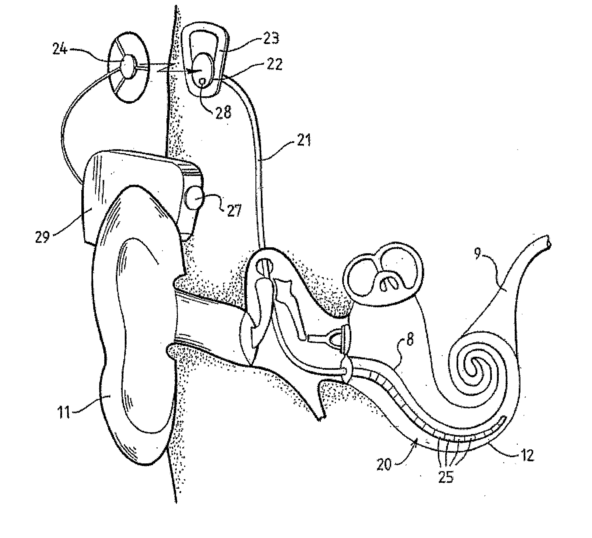
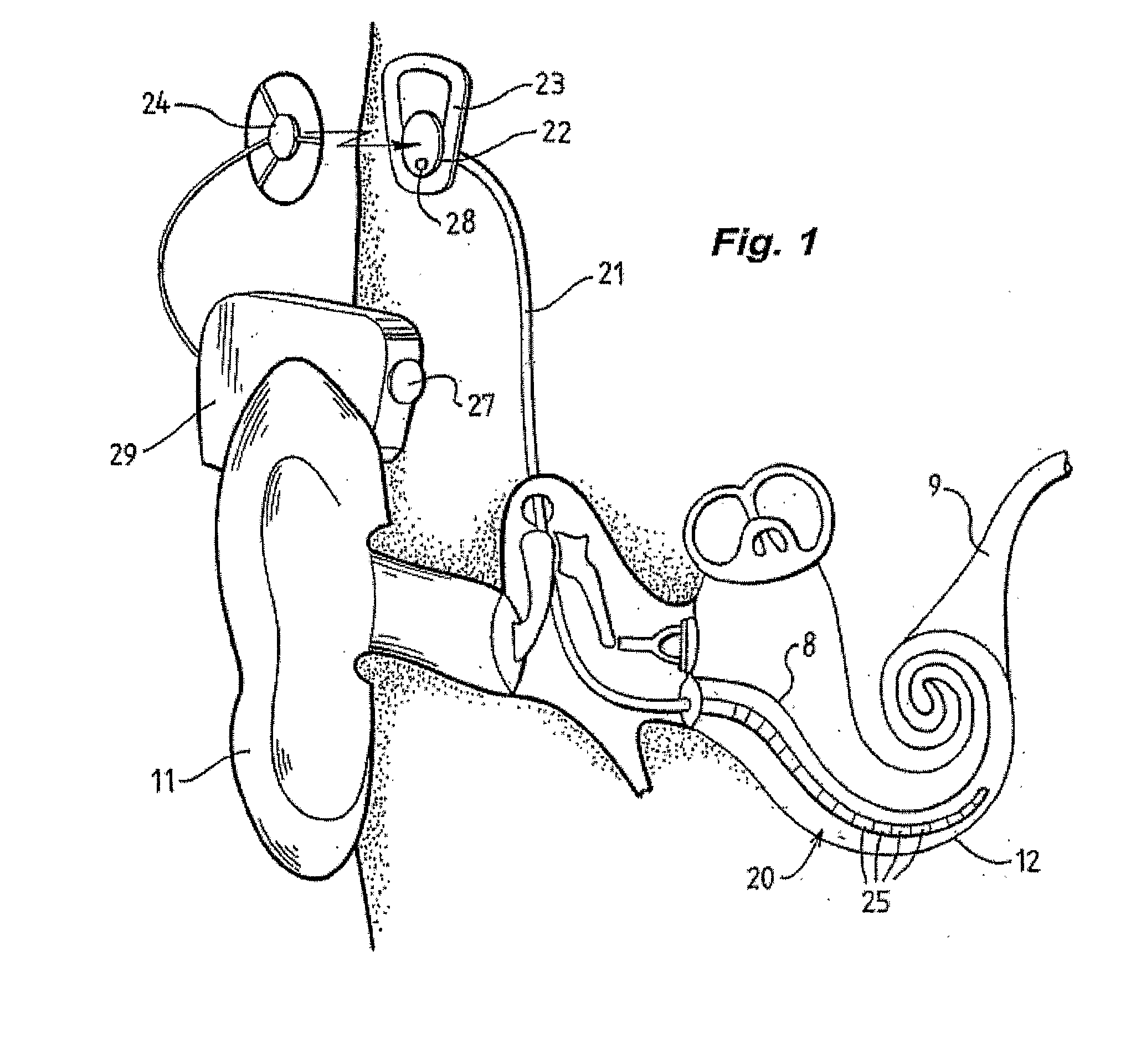
[0023]Before describing the features of the present invention, it is appropriate to briefly describe the construction of a cochlear implant system with reference to FIG. 1.

[0024]Cochlear implants typically consist of two main components, an external component including a sound processor 29, and an internal component including an implanted receiver and stimulator unit 22. The external component includes an on-board microphone 27. The sound processor 29 is, in this illustration, constructed and arranged so that it can fit behind the outer ear 11. Alternative versions may be worn on the body or it may be possible to provide a folly implantable system which incorporates the speech processor and the microphone into the implanted stimulator unit. Attached to the sound processor 29 is a transmitter coil 24 which transmits electrical signals to the implanted unit 22 via an RF link.

[0025]The implanted component includes a receiver coil 23 for receiving power and data from the transmitter coi...


PUM


Abstract

A method for detecting an electrode fault in a cochlear prosthesis. A voltage between the implanted electrode and a reference node is measured. It is then determined whether the voltage measured has been affected by an electrical leakage path between the electrode and a power supply node.

Description

CROSS-REFERENCE TO RELATED APPLICATIONS[0001]The present application is a National Stage Application of International Application No. PCT / AU2009 / 000001, filed on Jan. 2, 2009, entitled “Electrode Fault Detection,” which claims priority from Australian Patent Application No. Australian Provisional Patent Application No. 2008900008 filed on 2 Jan. 2008, the contents of which are hereby incorporated by reference herein.BACKGROUND[0002]1. Field of the Invention[0003]The present invention relates generally to cochlear implants, and in particular, to the in situ identification of electrode faults.[0004]2. Related Art[0005]Cochlear prostheses or cochlear implant systems bypass the hair cells in the cochlea and directly deliver electrical stimulation to the auditory nerve fibres, thereby allowing the brain to perceive a hearing sensation resembling the natural hearing sensation normally delivered to the auditory nerve. U.S. Pat. No. 4,532,930, provides a description of one type of cochlear ...

Claims


Application Information

Patent Timeline
Patent Type & Authority Applications(United States)
IPC IPC(8): G01R31/02
CPCA61B5/053A61B5/063G01R31/025A61N1/36032A61N1/37252A61N1/025G01R31/52
Inventor TSAMPAZIS, KOSTAS IOANNISSALDANHA, ANDREWROTTIER, RIAAN
Owner TSAMPAZIS KOSTAS IOANNIS
Why Eureka
Try Eureka